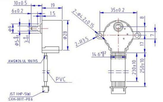
These stepper motors draw a lot of currents, hence a driver IC like the ULN2003 is required. We should look at the coil diagram below to see how to make this motor rotate.
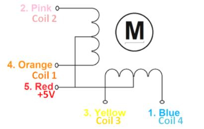
28-BYJ48 Diagram
As can be seen, the motor has four coils, one of which is connected to +5V (Red) while the others (Orange, Pink, Yellow, and Blue ) are taken out like wires. A steady +5V supply is delivered to the Red wire, and this +5V will only be across (energize) the coil if the other end of the coil is grounded. Only when the coils are energized (grounded) in a logical order can a stepper motor operate.
A microcontroller or a digital circuit can be used to program this logical sequence. The table below shows the order in which each coil should be triggered. The coil is retained at +5V in this case, and because both ends of the coil are at +5V (red and other ends), the coil will not be energized. Similarly, "0" indicates that the coil is grounded; now one end will be +5V and the other will be grounded, indicating that the coil is energized.