ATTENTION: Due to increased demand and order volume, processing time may take an additional 1-3 business days.
HomeCommunitySubject2N2646 PN Unijunction Transistor: Datasheet, Pinout and Equivalent

2N2646 PN Unijunction Transistor: Datasheet, Pinout and Equivalent

2N2646 is a general-purpose silicon PN Unijunction Transistor that is designed for general purpose industrial applications. This article mainly covers datasheet, current, equivalent, pinout, and other details about the 2N2646 transistor. Furthermore, there is a huge range of semiconductors, capacitors, resistors, and ICs in stock. Welcome your RFQ!

2147

Sep 26, 2021

Fanny Sander

UJT Unijunction Transistor Testing and Circuit Demo


2N2646 is a general-purpose silicon PN Unijunction Transistor that is designed for general purpose industrial applications. This article mainly covers datasheet, current, equivalent, pinout, and other details about the 2N2646 transistor. Furthermore, there is a huge range of semiconductors, capacitors, resistors, and ICs in stock. Welcome your RFQ!


2N2646

Inquiry
Min.: 1 Mult.: 1
Price not displayed? Not available to buy online? Please send an RFQ, and we will respond immediately.
Quick Links

What is 2N2646?

The 2N2646 is a silicon PN Unijunction Transistor that can be used in a variety of industrial applications. The device is commonly used as a triggering device and is not designed to drive high-current loads.

This transistor is made out of n-type semiconductors, with the length of the p-type material controlled to help fix the intrinsic standoff ratio parameter. Emitter, base, and collector are the three terminals on a typical 2n2646 UJT.

2N2646 Pinout

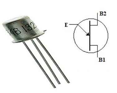
The conductive casing is also connected to a terminal on the 2N2646, making it a three-terminal device. The following is the 2N2646 Pinout diagram of the 2N2646 Unijunction transistor.

2N2646 Pinout


Pin Name Description
1 Base 1 Normally connected to   Power
2 Emitter An emitter is used for   triggering transistor ON and OFF
3 Base 2 Normally connected to   Load
  Case Connected to Base 2   pin internally

2N2646 CAD Model

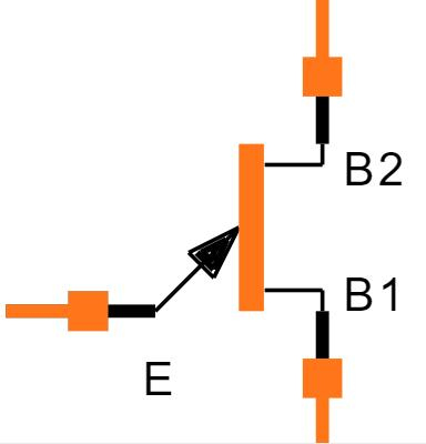
2N2646 Symbol


2N2646 Footprint

Specifications

NEW JERSEY SEMICONDUCTOR PRODUCTS INC 2N2646 technical specifications, attributes, parameters and parts with similar specifications to NEW JERSEY SEMICONDUCTOR PRODUCTS INC 2N2646.

2N2646 Tech Specifications

NEW JERSEY SEMICONDUCTOR PRODUCTS INC 2N2646 technical specifications, attributes, parameters and parts with similar specifications to NEW JERSEY SEMICONDUCTOR PRODUCTS INC 2N2646.

Product Attribute Attribute Value
RoHS StatusNon-RoHS Compliant
Product Attribute Attribute Value
0 Products View Similar

2N2646 Features

  • Low Peak Point Current: 5A (Max)

  • Low Emitter Reverse Current:005A (Typ)

  • Maximum voltage between two bases (VB2B1): 35V

  • Maximum emitters reverse voltage (VB2E): 30V

  • Maximum RMS emitter current (Ie): 50mA

  • Maximum peak emitter current (Ie): 2A

  • Operating temperature range: -65ºC to +150ºC

  • Maximum power dissipation: 300mW

  • Passivated Surface for Reliability & Uniformity

  • Available as “HR” (high reliability)

  • Available as non-RoHS (Sn/Pb plating)


2N2646 Applications

  • Timing circuit

  • Voltage detector

  • SCR firing circuits

  • Hobby projects

  • Phase control circuit

  • Sawtooth wave generator

  • Relaxation oscillator

  • General-purpose industrial applications

Where to Use 2N2646 Uni Junction Transistor

The 2N2646 is mostly employed in the design of firing circuits (for Silicon Controlled Rectifiers) rather than amplifier circuits such as transistors. Other applications that demand a guaranteed minimum pulse amplitude, as well as a low emitter leakage current and a low peak point emitter current (trigger current), favor the device. Many low-cost industrial applications use the 2N2646 transistor.

How to Use 2N2646 Uni Junction Transistor

The circuit diagram employing the 2N2646 unijunction transistor is given below. This circuit runs on 9V to 12V DC. A 9V to 12V battery, 2N2646 UJT, LED, 10K and 390 resistors, breadboard, and connecting wires are all needed to make this circuit.

2N2646 Circuit


In this circuit, a 390-ohm resistor is primarily utilized to limit the flow of current via the transistor and LED. The R1 and C1 parameters are mostly responsible for the LED flashing frequency. We can conduct some short experiments using these variables to determine the appropriate LED flashing rate.


We can use any value between 10K and 1M for the resistor 'R1.' In the circuit above, the resistor 'R1' is a 1M potentiometer or variable resistor, while the capacitor 'C1' can be any value between 1uF and 100uF.

Working of 2N2646 Uni Junction Transistor

When this transistor is turned on, the emitter current is allowed to increase until it is limited by the power supply in the emitter terminal. Because of its negative resistance, this transistor can also be used as an oscillator.

A potential drop occurs when a positive supply is applied to the two base terminals of this transistor. Once the emitter voltage is increased one diode voltage above the voltage where P-type material diffusion occurs, current will flow from the emitter terminal to the base.

As a result of the additional current on the base region, the resistance between the emitter (E) and the base region is reduced, and the UJT's conductivity improves. As a result of the resistance drop, the emitter terminal will connect in forwarding bias, allowing more current to be injected. As a result of the resistance drop, the UJT will be able to operate above negative resistance. As a result, it is extremely useful for oscillators’ circuits.

2N2646 Mechanical Outline

2N2646 Mechanical Outline

2N2646 Manufacturer

New Jersey Semiconductor has been designing, manufacturing, and producing highly reliable electronic devices since 1957. Our mission is to supply you with high-quality, cost-effective discrete devices for commercial, industrial, and military applications.

Frequently Asked Questions

What is 2N2646 used for?
The 2N2646 is designed for use in pulse and timing circuits, sensing circuits, and thyristor trigger circuits.
How does 2N2646 work?
The current will flow from the emitter terminal to the base, once the voltage of the emitter is increased one diode voltage over the voltage wherever P-type material diffusion occurs. So, this resistance drop will make the UJT operate above the negative resistance
FAQ
What is 2N2646 used for?
The 2N2646 is designed for use in pulse and timing circuits, sensing circuits, and thyristor trigger circuits.
How does 2N2646 work?
The current will flow from the emitter terminal to the base, once the voltage of the emitter is increased one diode voltage over the voltage wherever P-type material diffusion occurs. So, this resistance drop will make the UJT operate above the negative resistance

TAGS

Share