As a switch
Following is a proteus simulation of 2N5089 to control an LED. The two different circuits represent the working of the circuit when the base voltage is the same as the emitter and when the base voltage is greater than the emitter voltage.
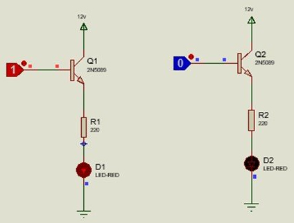
In the first circuit, the collector is provided with a Vcc of 12 volts. The base is connected to a logic toggle. The led is placed at the emitter terminal following 220 ohms of a resistor to limit the excess forward current to avoid led damage. When the logic is turned on, the forward current flows and the led glows. On the contrary, when the logic is turned off, when voltage is not given to the base terminal, the base potential is the same as the emitter potential, so the led loses its luminosity, as shown by the second circuit.
As an amplifier
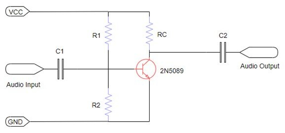
Above is the circuitry of 2N5089 as an amplifier. For the amplification of the signal, a common emitter configuration is used. This configuration has a high gain. The base terminal is applied with an input signal, and the collector is provided with some volts to turn on the active mode and operate the transistor as an amplifier. An audio signal is an AC signal. Coupling capacitors are used to avoid the distortion of the signals, which affects the audio quality by displaying high input impedance to low-frequency components.
A capacitor is also placed in series with the output to block the unnecessary DC components at the load/output. RC resistor controls the flow of collector current to control the gain of the amplifier. It is responsible for the frequency response of the circuitry as well. As a result, a small weak radio signal after passing through an NPN amplifier transistor is received as an inverted, amplified radio signal with a high voltage and power gain with fine quality and finds its applications in low noise, audio amplification systems.