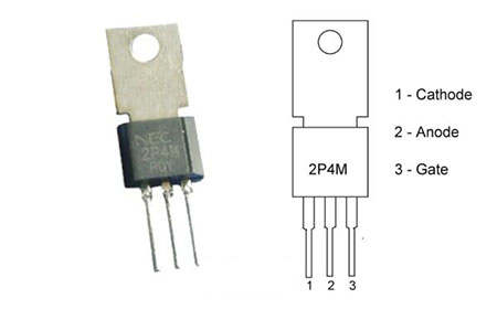
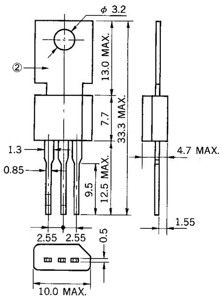
The application with a simple circuit diagram using the 2P4M SCR is illustrated in the figure below. The components required for this application circuit of the device are 2P4M SCR, Buttons -2, Resistors & Voltage source.
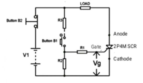
2P4M SCR Circuit
The DC voltage source is depicted as V1 in the circuit diagram above, as is the gate voltage, which represents the trigger voltage at the device's gate.
The load resistor is connected to the SCR in series.
By default, when button B2 is pressed, it closes and breaks the circuit.
The load is linked to the SCR's anode terminal.
The SCR's cathode terminal is connected to the source's opposite end.
The button B1 is not pressed in the beginning, and the SCR is in a non-conducting condition due to the lack of gate voltage. The total voltage drop across the device appears when Vg=0V or no trigger is applied to the SCR's gate terminal, and the voltage at the load is 0V (Vload=0V). This is depicted in the graph above. This condition is maintained until a voltage pulse is applied to the device's gate. Only when button B1 is pushed is this state feasible.
Consider the case where button B1 is touched at time T1. The 2P4M SCR conducts in this state, and the total voltage appears across the load, as shown in the graph above. The SCR is triggered ON and remains in the conducting mode due to the DC power source. Even if the gate voltage is removed once the SCR is triggered, the device conducts.
The current flowing through the 2P4M SCR should now be '0' for some time in order to recover the device in a high resistance state. When the current is '0' or cuts off, the device's stored charge is dissipated, allowing it to return to its initial state, which is forward blocking.
The button B2 should be pressed to bring the current flowing through the device to '0.' The circuit loop is broken and the current flowing in the gadget becomes '0' when button B2 is pressed once. As a result, the voltage across the load drops to zero, and the device begins to restore its condition, as seen in the graph above. This is because when the B2 is hit, the loop breaks.
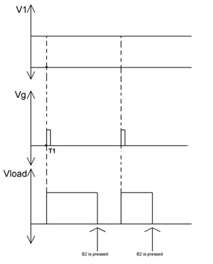
2P4M SCR Waveform
The gadget stops the forward DC voltage and waits for the trigger voltage once you release button B2 (gate pulse). Until the button B2 is touched, the load voltage will be '0.' The load voltage after the first and second trigger pulses is shown in the graph above. This cycle of triggering and breaking continues.