ATTENTION: Due to increased demand and order volume, processing time may take an additional 1-3 business days.
HomeCommunitySubject4N25 Optocoupler: Pinout, Circuit and Datasheet

4N25 Optocoupler: Pinout, Circuit and Datasheet

VISHAY 4N25 Transistor Output Optocoupler, 1 Channel, DIP, 6 Pins, 60 mA, 5 kV, 20 %

5043

Aug 4, 2021

Bernice Sally

Proteus #1 - Zero Cross Detector using 4N25 Optocoupler.


VISHAY 4N25 Transistor Output Optocoupler, 1 Channel, DIP, 6 Pins, 60 mA, 5 kV, 20 %

4N25 is an optocoupler >optocoupler for general purpose applications.This article mainly introduce its pinout, circuit, datasheet and other detailed information about Vishay Semiconductor 4N25.


4N25

Inquiry
Min.: 1 Mult.: 1
Price not displayed? Not available to buy online? Please send an RFQ, and we will respond immediately.
Quick Links

4N25 Description

The 4N25 series is industry standard single channel phototransistor coupler. This series includes the 4N25, 4N26, 4N27, 4N28. 

Each optocoupler consists of gallium arsenide infrared LED and a silicon NPN phototransistor. 

It contains a light emitting diode optically coupled to a photo-transistor and is packaged in a 6-pin DIP pack- age and available in wide-lead spacing option and lead bend SMD option.

4N25 Pinout

4N25 CAD Model

Symbol


Footprint


3D Model

4N25 Features

1.IR LED Forward Voltage for turning ON: 1.25V-1.5V (Typically 1.3V, 1.5V being absolute  maximum forward voltage)

2.IR LED Forward Current during ON: 10mA - 60mA (Typically 10mA, 60mA being absolute maximum forward current)

3.IR LED Reverse Voltage Maximum: 5V

4.IR LED Reverse Current Maximum: 100uA

5.Maximum voltage across COLLECTOR and EMITTER of TRANSISTOR: 70V

6.Maximum current allowed trough TRANSISTOR COLLECTOR: 100mA

7.Typical Rise Time: 2us

8.Typical Fall Time: 2us

9.No additional power needed to be applied for chip for making it work.

10.Isolation test voltage 5000 VRMS

11.Interfaces with common logic families

12.Input-output coupling capacitance < 0.5 pF

13.Industry standard dual-in-line 6 pin package

14.Compliant to RoHS directive 2002/95/EC and in accordance to WEEE 2002/96/EC

Specifications

Vishay Semiconductor Opto Division 4N25 technical specifications, attributes, parameters and parts with similar specifications to Vishay Semiconductor Opto Division 4N25.

4N25 Tech Specifications

Vishay Semiconductor Opto Division 4N25 technical specifications, attributes, parameters and parts with similar specifications to Vishay Semiconductor Opto Division 4N25.

Product Attribute Attribute Value
Factory Lead Time14 Weeks
Contact PlatingTin
MountPCB, Through Hole
Mounting TypeThrough Hole
Package / Case6-DIP (0.300, 7.62mm)
Number of Pins6Pins
Supplier Device Package6-DIP
Collector-Emitter Breakdown Voltage30V
Collector-Emitter Saturation Voltage500mV
Current Transfer Ratio-Min20% @ 10mA
Number of Elements1 Element
Operating Temperature-55°C~100°C
PackagingTube
Published2014
Part StatusActive
Moisture Sensitivity Level (MSL)1 (Unlimited)
Max Operating Temperature100°C
Product Attribute Attribute Value
Min Operating Temperature-55°C
Max Power Dissipation150mW
Base Part Number4N25
Approval AgencyUL, VDE
Voltage - Isolation5000Vrms
Output Voltage30V
Output TypeTransistor with Base
Number of Channels1Channel
Power Dissipation150mW
Voltage - Forward (Vf) (Typ)1.3V
Input TypeDC
Forward Current60mA
Max Output Voltage30V
Output Current per Channel50mA
Rise Time2s
Forward Voltage1.3V
Fall Time (Typ)2 s
Product Attribute Attribute Value
Collector Emitter Voltage (VCEO)30V
Max Collector Current100mA
Rise / Fall Time (Typ)2μs 2μs
Reverse Breakdown Voltage5V
Max Input Current60mA
Current - DC Forward (If) (Max)60mA
Input Current50mA
Max Junction Temperature (Tj)125°C
Vce Saturation (Max)500mV
Current Transfer Ratio50 %
Height4.8mm
REACH SVHCUnknown
Radiation HardeningNo
RoHS StatusROHS3 Compliant
Lead FreeLead Free
0 Products View Similar

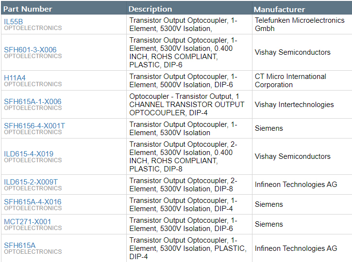
4N25 Alternatives

How to use 4N25?

4N25 OPTOCOUPLER IC has two components integrated in it. One is INFRARED DIODE and another of INFRARED PHOTOTRANSISTOR. The IR DIODE is connected between terminals 1 and 2, the PHOTOTRANSISTOR is connected at terminals 4, 5 and 6.The internal setup of two components can be seen below. The IR radiation emitted by IR LED will not be visible outside the chip. The whole issue of radiation will be working under background.

For understanding the OPTOCOUPLER we will consider a circuit shown below.

We will get the +3.3Voltage pulses from a microcontroller and these are driven to the POSITIVE of IR DIODE. When IR DIODE gets powered it will emit Infrared rays internally, when these rays fell on the PHOTOTRANSISTOR the transistor gets turned ON. When transistor gets tuned ON the current flows through load circuit and the voltage will be seen across the motor. Thus the motor rotates when microcontroller circuit provides HIGH logic to the 4N25 chip.


When the controller output goes LOW, the IR DIODE input goes LOW. With that the IR DIODE stops emitting radiation internally.  Since radiation is cutoff the PHOTOTRANSISTOR gets turned OFF since the radiation acts as BASE TRIGGER. So its LOW RESISTANCE state to HIGH RESISTANCE states. With HIGH RESISTANCE the complete supply voltage appears across the transistor and current flow in the load circuit gets ZERO. So the motor stops rotating. Thus the motor stops rotating when the microcontroller input to 4N25 gets LOW.


In this circuit you can see the motor draws power from the +12V battery source and not from the controller circuit. The PHOTOTRANSISTOR side secondary circuit here is in complete isolation with the CONTROLLER-PHTODIODE primary circuit. The resistors here are placed for limiting the currents in the circuit. Make a note the resistance values changed depending on voltages.


4N25 Applications

● DC motor speed control

● Lighting systems

● PWM applications

● AC mains detection

● Reed relay driving

● Switch mode power supply feedback

● Telephone ring detection

● Logic ground isolation

● Logic coupling with high frequency noise rejection

4N25 Package

4N25 Manufacturer

Vishay Intertechnology, Inc. is an American manufacturer of discrete semiconductors and passive electronic components founded by Polish-born businessman Felix Zandman. Vishay has manufacturing plants in Israel, Asia, Europe, and the Americas where it produces rectifiers, diodes, MOSFETs, optoelectronics, selected integrated circuits, resistors, capacitors, and inductors.Vishay is one of the world's foremost manufacturers of power MOSFETs.They have a wide range of power electronic applications, including portable information appliances, internet communications infrastructure, power integrated circuits, cell phones, and notebook computers.


Datasheet PDF

Download datasheets and manufacturer documentation for Vishay Semiconductor Opto Division 4N25.

4N25 Documents

Download datasheets and manufacturer documentation for 4N25

Datasheets
4N25-28

Frequently Asked Questions

1.How to connect the 4N25 pins?
ANODE is connected to the positive electrode, CATHODE is connected to the negative electrode, NO CONNECTION is not connected, EMITTER is connected to the emitter, COLLECTOR is connected to the collector, and BASE is connected to the base.
2.What is the working principle of the optocoupler chip 4N25?
The principle is to use light as a medium to transmit electrical signals. When the input terminal is powered on, the illuminator emits light, and after the light receiver receives the light, it generates photocurrent, which flows out from the output terminal, thus realizing the "electricity-optical-electricity" conversion.
3.Can optocoupler 4N25 replace PC817?
PC817 is a linear optocoupler, 4N25 is a non-linear optocoupler, and has a higher response speed than PC817. If used in digital circuits, it can replace PC817, but the PCB package needs to be changed. If used in a linear circuit, such as the feedback of a switching power supply, it cannot be replaced.
FAQ
1.How to connect the 4N25 pins?
ANODE is connected to the positive electrode, CATHODE is connected to the negative electrode, NO CONNECTION is not connected, EMITTER is connected to the emitter, COLLECTOR is connected to the collector, and BASE is connected to the base.
2.What is the working principle of the optocoupler chip 4N25?
The principle is to use light as a medium to transmit electrical signals. When the input terminal is powered on, the illuminator emits light, and after the light receiver receives the light, it generates photocurrent, which flows out from the output terminal, thus realizing the "electricity-optical-electricity" conversion.
3.Can optocoupler 4N25 replace PC817?
PC817 is a linear optocoupler, 4N25 is a non-linear optocoupler, and has a higher response speed than PC817. If used in digital circuits, it can replace PC817, but the PCB package needs to be changed. If used in a linear circuit, such as the feedback of a switching power supply, it cannot be replaced.

TAGS

Share