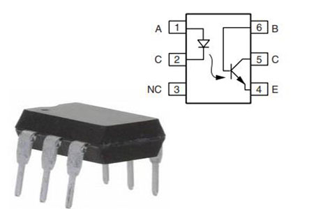
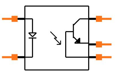
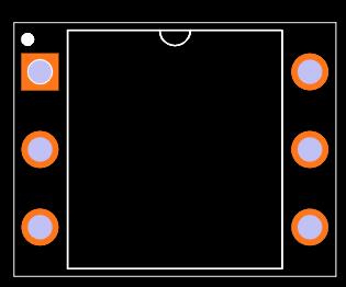
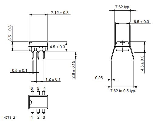
The Photo Transistor and the IR Diode are the two major components of the 4N28 Optocoupler. This diode can be linked between two terminals (1&2), while the phototransistor is attached between the remaining three terminals (4, 5, and 6). To construct an application circuit, this optocoupler IC is coupled to a few simple components.
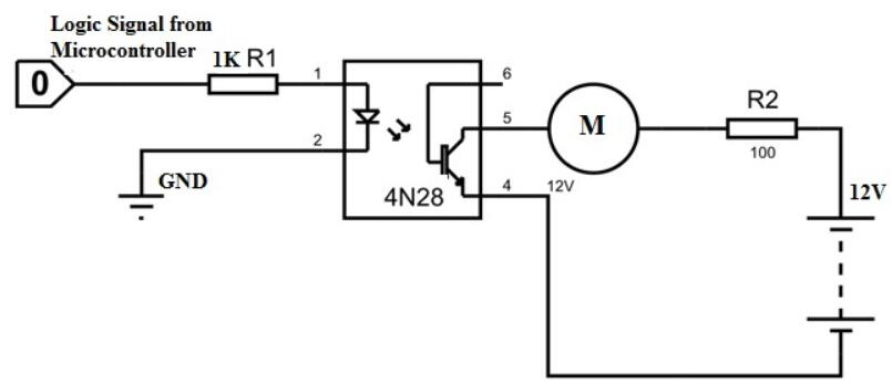
4N28 Circuit
In the circuit above, the microcontroller sends trigger pulses to the optocoupler IC, which acts as input signals. The collector terminal is connected to an electric motor, which acts as an output.
The IR diode will be engaged when it receives a +3.3V input signal from the controller.
When it receives electricity, it will generate infrared signals that will trigger the phototransistor. When the transistor is turned on, current flows through the load circuit, and a voltage appears across the electric motor. As a result, once the microcontroller generates HIGH logic toward the IC at the input, this motor will turn.
When the microcontroller's trigger pulses are turned off, the infrared diode's input is turned off. As a result, no power is supplied to the IR DIODE, and it ceases to emit emissions. When no emission is present, the phototransistor is turned off, and the transistor switches from low to high resistance.
The entire voltage supply will come out across the transistor due to excessive resistance, and the current flow within the load circuit will be ZERO. As a result, whenever the microcontroller delivers less logic to the IC at the input, the motor stops rotating.
Both the motor and the transistor act as load circuits in the aforementioned circuit, while the controller and the infrared diode act as trigger circuits. The voltage source employed in the circuit can be used to provide power to the motor.