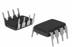
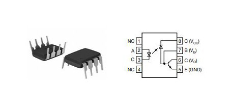
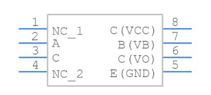
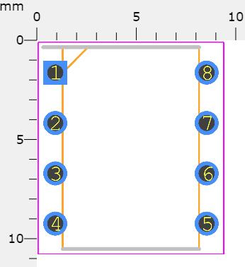
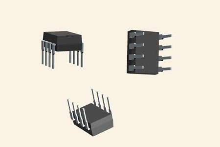
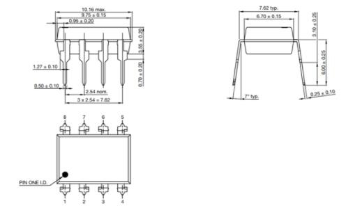
Despite the fact that the 6N135 can work with both AC and DC, It works with a 5V supply voltage and is often used in digital circuits. From the datasheet, a typical application circuit for 6N135 is given below.
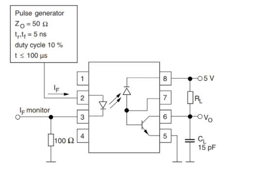
How to use 6N135
The 0.1uF bypass capacitor is connected to the supply rail. For the IC to respond, the input signal must have an impedance of at least 50 ohms and rise and fall times of at least 5nS. The input signal can be explored (if necessary) on pin 3, and the pull-down resistor 100 is only required if the signal is connected to a scope.
As previously stated, the output (pin 6) is an open-drain transistor, which means it can either sink or float current. To minimize floating, a pull-up resistor RL should be used. The value of RL can range from 330 ohms to 4K, depending on the load attached.
Pin 7 is the Enable pin, which has a built-in pull-up resistor, therefore the IC is enabled by default when powered. When connected to the ground, the output is disabled. The pin can be used to make strobe circuits and other things. The truth table below will help you understand how Enable pin works.
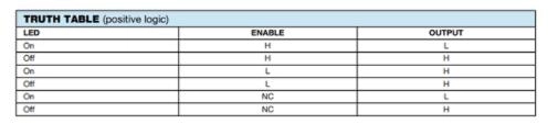
Truth Table
Because the output is open drain, the output will be low while the input is high and vice versa. Another factor to consider is the propagation time, which is important because the IC is typically used for quick switching. When the input is logic on, the output is only turned off after (TPHL), and when the input is logic off, the output is only turned on after (TPHL) (TPLH). The switching diagram below demonstrates the same concept.
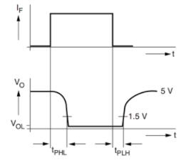
Switching Diagram