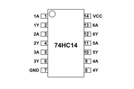
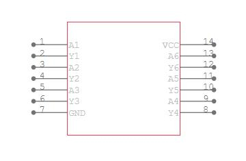
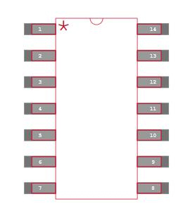
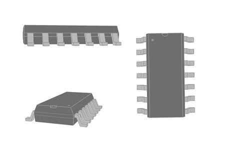
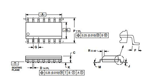
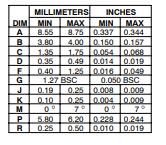
As previously stated, the 74HC14 includes six INVERTING SCHMITT TRIGGER GATES that can be used individually. The logic diagram can be summarized as follows.
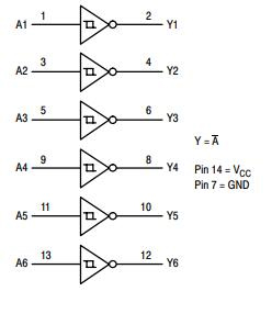
74HC14 Logic Diagram
Now, to better understand how gates work, let's take a single gate and attach the power to the chip. Also, at the input, provide an analogue signal.
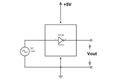
74HC14 Circuit
As shown in the circuit, we are giving a sinusoidal wave at the input and taking Vout as the output of the gate. Once we draw the input and output graph we will have something like this.
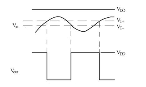
74HC14 Trigger Application
The Schmitt Trigger operates on a very basic principle: the output of an inverting Schmitt Trigger is LOW only when the input signal voltage level crosses the threshold voltage (+Vt).
As illustrated in the diagram, the output voltage (Vout) is HIGH until the input voltage (Vin) surpasses the threshold voltage (Vt+). The output voltage becomes LOW once it hits the threshold voltage. Until the input voltage falls below the low threshold voltage, the output voltage remains low (Vt-). The output voltage hits HIGH once it reaches that point. This cycle continues.
As illustrated in the graph, when a sinusoidal signal is used as an input, the result is a square wave. Each gate can be used in this manner to obtain the required output.