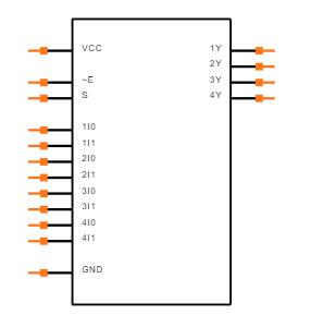
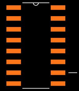
It's quite simple to use the 74HC157 IC. The IC's operational voltage ranges from 2 to 6 volts, so choose one (usually 5 volts) and power it with the Vcc and Ground pins. For regular IC functioning, the Enable pin must be connected to the ground. Therefore, you can either ground it permanently or link it to an MCU/MPU to turn on or off the Multiplexers as needed.
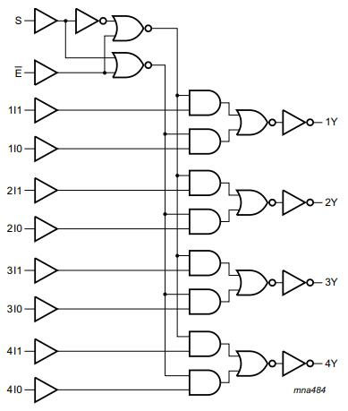
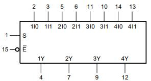
This IC contains four 2:1 multiplexers, but for the sake of simplicity, we'll assume we're just utilizing one of them. Because the multiplexer is a 2:1 multiplexer, it can accept two inputs. These two inputs are connected to the pins Input A (also known as Input I0) and Input B (also known as Input I1). The multiplexer's output is connected to the output pin Y. The chosen line (pin 1) determines which of the two inputs goes to the output pin. Input A will be reflected on the output pin Y if the Select Line is low (logic 0), and Input B will be reflected on the output pin Y if the Select Line is high (logic 1). The following is a 74HC157 multiplexer circuit.
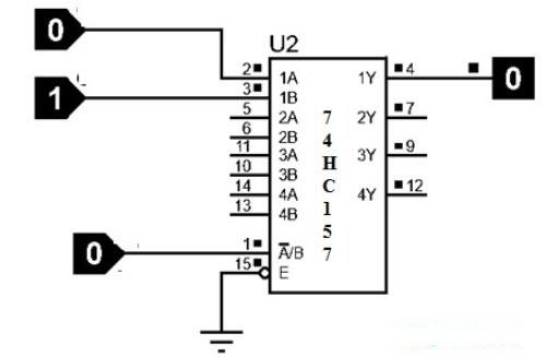
74HC157 multiplexer circuit
This IC contains four 2:1 multiplexers, but for the sake of simplicity, we'll assume we're just utilizing one of them. Because the multiplexer is a 2:1 multiplexer, it can accept two inputs. These two inputs are connected to the pins Input A (also known as Input I0) and Input B (also known as Input I1). The multiplexer's output is connected to the output pin Y. The chosen line (pin 1) determines which of the two inputs goes to the output pin. Input A will be reflected on the output pin Y if the Select Line is low (logic 0), and Input B will be reflected on the output pin Y if the Select Line is high (logic 1).
| Enable |
Select I/P |
Data Inputs |
Data Inputs |
Output (157) |
Output (158) |
| E’ |
S |
I0 |
I1 |
Y |
Y’ |
| H |
X |
X |
X |
L |
H |
| L |
L |
L |
X |
L |
H |
| L |
L |
H |
X |
H |
L |
| L |
H |
X |
L |
L |
H |
| L |
H |
X |
H |
H |
L |