74HC154 74HC193
IC COUNTER U/D 4BIT BIN 16SOIC
74HC193 is a 4-bit synchronous binary up/down counter.This article mainly introduce Pinout, datasheet PDF and other detailed imformation about Nexperia 74HC193.

IC COUNTER U/D 4BIT BIN 16SOIC 74HC193 is a 4-bit synchronous binary up/down counter.This article mainly introduce Pinout, datasheet PDF and other detailed imformation about Nexperia 74HC193.
947
Jun 14, 2021
Eartha
74HC154 74HC193
IC COUNTER U/D 4BIT BIN 16SOIC
74HC193 is a 4-bit synchronous binary up/down counter.This article mainly introduce Pinout, datasheet PDF and other detailed imformation about Nexperia 74HC193.
74HC193D-Q100J
| Quantity | Unit Price | Ext. Price |
|---|---|---|
| 1+ | $1.75982 | $1.76 |
| 10+ | $1.66021 | $16.6 |
| 100+ | $1.56623 | $156.62 |
| 500+ | $1.47758 | $738.79 |
| 1000+ | $1.39394 | $1393.94 |
The 74HC193 is a 4-bit synchronous binary up/down counter. Separate up/down clocks, CPU and CPD respectively, simplify operation.
The outputs change state synchronously with the LOW-to-HIGH transition of either clock input. If the CPU clock is pulsed while CPD is held HIGH, the device will count up. If the CPD clock is pulsed while CPU is held HIGH, the device will count down.
Only one clock input can be held HIGH at any time to guarantee predictable behavior. The device can be cleared at any time by the asynchronous master reset input (MR); it may also be loaded in parallel by activating the asynchronous parallel load input (PL). The terminal count up (TCU) and terminal count down (TCD) outputs are normally HIGH.
When the circuit has reached the maximum count state of 15, the next HIGH-to-LOW transition of CPU will cause TCU to go LOW. TCU will stay LOW until CPU goes HIGH again, duplicating the count up clock. Likewise, the TCD output will go LOW when the circuit is in the zero state and the CPD goes LOW. The terminal count outputs can be used as the clock input signals to the next higher order circuit in a multistage counter, since they duplicate the clock waveforms. Multistage counters will not be fully synchronous, since there is a slight delay time difference added for each stage that is added.
The counter may be preset by the asynchronous parallel load capability of the circuit. Information present on the parallel data inputs (D0 to D3) is loaded into the counter and appears on the outputs (Q0 to Q3) regardless of the conditions of the clock inputs when the parallel load (PL) input is LOW. A HIGH level on the master reset (MR) input will disable the parallel load gates, override both clock inputs and set all outputs (Q0 to Q3) LOW.
If one of the clock inputs is LOW during and after a reset or load operation, the next LOW-to-HIGH transition of that clock will be interpreted as a legitimate signal and will be counted. Inputs include clamp diodes. This enables the use of current limiting resistors to interface inputs to voltages in excess of VCC.
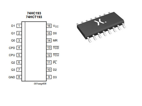
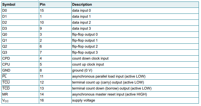
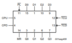
Pin Description
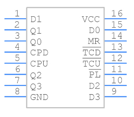
Symbol
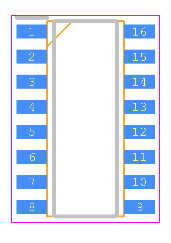
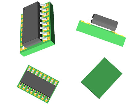
Footprint
3D Model
1.Input levels:
(1)For 74HC193: CMOS level
(2)For 74HCT193: TTL level
2.Synchronous reversible 4-bit binary counting
3.Asynchronous parallel load
4.Asynchronous reset
5.Expandable without external logic
6.Complies with JEDEC standard no. 7A
7.ESD protection:
(1)HBM JESD22-A114F exceeds 2000 V
(2)MM JESD22-A115-A exceeds 200 V.
8.Multiple package options
9.Specified from -40 °C to +85 °C and -40 °C to +125 °C.
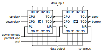
Application for cascaded up/down counter with parallel load
Nexperia USA Inc. 74HC193D-Q100J technical specifications, attributes, parameters and parts with similar specifications to Nexperia USA Inc. 74HC193D-Q100J.
Nexperia USA Inc. 74HC193D-Q100J technical specifications, attributes, parameters and parts with similar specifications to Nexperia USA Inc. 74HC193D-Q100J.
| Product Attribute | Attribute Value | |
|---|---|---|
| Factory Lead Time | 4 Weeks | |
| Contact Plating | Gold | |
| Mount | Surface Mount | |
| Mounting Type | Surface Mount | |
| Package / Case | 16-SOIC (0.154, 3.90mm Width) | |
| Number of Elements | 1 Element | |
| Usage Level | Automotive grade | |
| Operating Temperature | -40°C~125°C | |
| Packaging | Tape & Reel (TR) | |
| Series | 74HC | |
| Published | 2007 | |
| Part Status | Active | |
| Moisture Sensitivity Level (MSL) | 1 (Unlimited) |
| Product Attribute | Attribute Value | |
|---|---|---|
| Number of Terminations | 16Terminations | |
| Voltage - Supply | 2V~6V | |
| Terminal Position | DUAL | |
| Terminal Form | GULL WING | |
| Number of Functions | 1Function | |
| Supply Voltage | 5V | |
| Base Part Number | 74HC193 | |
| Pin Count | 16 | |
| Operating Supply Voltage | 5V | |
| Supply Voltage-Max (Vsup) | 6V | |
| Supply Voltage-Min (Vsup) | 2V | |
| Quiescent Current | 8μA | |
| Reset | Asynchronous |
| Product Attribute | Attribute Value | |
|---|---|---|
| Family | HC/UH | |
| Logic Function | Counter | |
| Direction | Up, Down | |
| Logic Type | Binary Counter | |
| Number of Bits per Element | 4Bits per Elements | |
| Trigger Type | Positive Edge | |
| Propagation Delay (tpd) | 325 ns | |
| Count Rate | 49MHz | |
| Timing | Synchronous | |
| Length | 9.9mm | |
| Width | 3.9mm | |
| Radiation Hardening | No | |
| RoHS Status | ROHS3 Compliant |
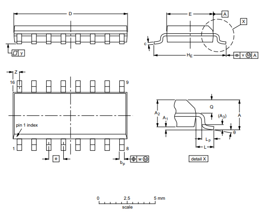
SO-16: Plastic small outline package; 16 leads; body with 3.9mm
Functional Diagram
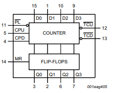
Logic Symbol
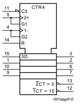
IEC Logic Symbol
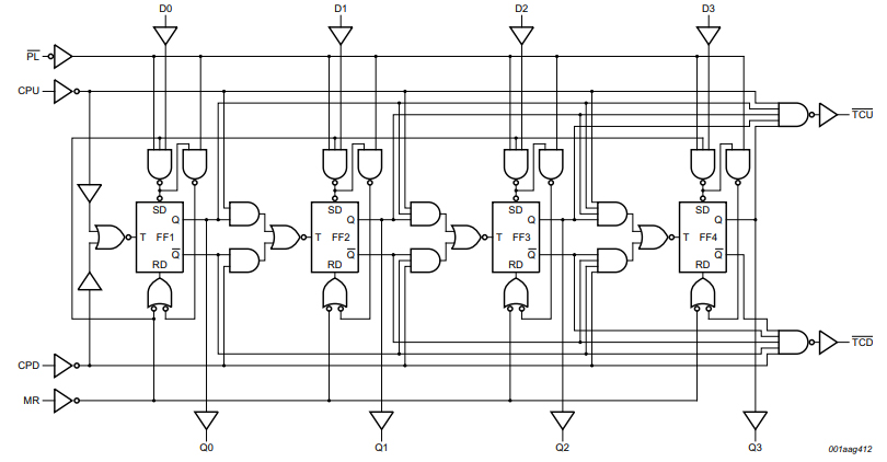
Logic Diagram
Nexperia is a dedicated global leader in Discretes, Logic and MOSFETs devices. This new company became independent at the beginning of 2017. Focused on efficiency, Nexperia produces consistently reliable semiconductor components at high volume: 85 billion annually. The company’s extensive portfolio meets the stringent standards set by the Automotive industry. And industry-leading small packages, produced in their own manufacturing facilities, combine power and thermal efficiency with best-in-class quality levels. Built on over half a century of expertise, Nexperia has 11,000 employees across Asia, Europe and the U.S. supporting customers globally.
Download datasheets and manufacturer documentation for Nexperia USA Inc. 74HC193D-Q100J.
Download datasheets and manufacturer documentation for 74HC193D-Q100J
TAGS
Comments