ATTENTION: Due to increased demand and order volume, processing time may take an additional 1-3 business days.
HomeCommunitySubject74LS00 Quad 2 Input NAND Gate: Datasheet, Pinout and Schematic

74LS00 Quad 2 Input NAND Gate: Datasheet, Pinout and Schematic

74LS00 is a quad 2 input NAND Gate. This post mainly covers pinout, datasheet, schematics, logic, circuit, and more details about the 74LS00 gate. Furthermore, there is a huge range of semiconductors, capacitors, resistors, and ICs in stock. Welcome your RFQ!

3486

Sep 30, 2021

Enoch Hewlett

Switch based NAND gate and 7400 integrated circuit IC demonstration beginner learning electronics


74LS00 is a quad 2 input NAND Gate. This post mainly covers pinout, datasheet, schematics, logic, circuit, and more details about the 74LS00 gate. Furthermore, there is a huge range of semiconductors, capacitors, resistors, and ICs in stock. Welcome your RFQ!

74LS00

Inquiry
Min.: 1 Mult.: 1
Price not displayed? Not available to buy online? Please send an RFQ, and we will respond immediately.
Quick Links

74LS00 Description

The 74LS00 is one of the most well-known and fundamental logic gates. AND, OR, and NOT are the three types of gates. Each of the three gates has a unique internal circuit and serves a different purpose in each device. Other gates such as NAND, NOR, XOR, and XNOR can be created by combining these three circuits. Transistors, resistors, and capacitors can be used to create all of these gates. When we construct these circuits, the size of a single gate exceeds our expectations.

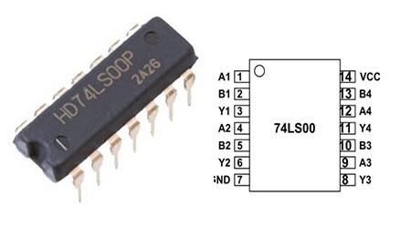
74LS00 Pinout

74LS00 Pinout


Pin No Pin Description
1 A1-INPUT
2 B1-INPUT
3 Y1-OUTPUT
4 A2-INPUT
5 B2-INPUT
6 Y2-OUTPUT
7 GND
8 Y3-OUTPUT
9 A3-INPUT
10 B3-INPUT
11 Y4-OUTPUT
12 A4-INPUT
13 B4-INPUT
14 VCC

74LS00 CAD Model

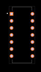
74LS00 Footprint

74LS00 Specifications

  • Operating voltage range: +4.75 to +5.25V

  • Maximum supply voltage: 7V

  • Maximum current allowed drawing through each gate output: 8mA

  • TTL outputs

  • Maximum ESD: 3.5KV

  • Typical Rise Time: 15ns

  • Typical Fall Time: 15ns

  • Operating temperature: 0°C to 75°C


74LS00 Tech Specifications

ROCHESTER ELECTRONICS LLC 74LS00 technical specifications, attributes, parameters and parts with similar specifications to ROCHESTER ELECTRONICS LLC 74LS00.

Product Attribute Attribute Value
Logic IC TypeDECADE COUNTER
Product Attribute Attribute Value
0 Products View Similar

74LS00 Features

  • It comes in a variety of packages, including SOIC, PDIP, and SOP.

  • It can be employed in systems with a high frequency.

  • This IC can be used as a NAND gate, but because of the NAND gate's universality, it can easily be transformed into other gates.

  • Because the IC's internal structure is based on TTL, its output is also TTL.


74LS00 Applications

  • General logic

  • Digital electronics

  • Computer and laptop

  • Server

  • ALU

  • Networking

  • Digital system

74LS00 Equivalents

Any two transistors can be modified to make a NAND gate, such as the SN54LS00, SN7400, or CD4011.


74LS00 Alternatives

74LS08, 74LS00CH,74LS00DC,74LS00J,74LS00N,74LS00NA,74LS00PC,74LS00W,901521-01,AMX3550,C74LS00P,DM74LS00N,EA33X8605,EAQ00-12100,ECG74LS00,GD74LS00,HD74LS00,HD74LS00P,HE-443-728

74LS00 Advantages

  • The IC features four NAND gates, each of which can be utilized for a different gate.

  • Because the NAND gate can be converted to a NOT gate by rearranging the pins, the 74LS00 can be utilized as an inverter.

  • The 74LS00 is one of the most affordable integrated circuits, making it more popular than other ICs.

  • Without the assistance of a microcontroller or processor, it could perform HIGH NAND speed operations in nanoseconds.


How to Use 74LS00

74LS00 2 input NAND Gate WORKING

The IC has four NAND gates; however, each NAND gate has two different types of internal structures. CMOS is the first, and PMOS is the second. When we observe the structure, it may appear to be changed, yet its primary function remains the same. Four transistors make up the CMOS NAND gate. The circuit is made up of transistors and a power source, and it produces the HIGH and LOW states depending on the input combinations. The NAND gate's internal construction is shown below.
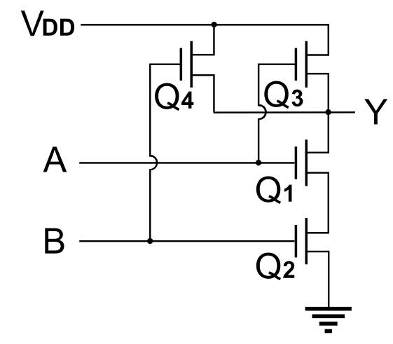
74LS00 Circuit


Q1 and Q2 will both be turned off. As a result, the total supply voltage is seen across transistors Q1 and Q2. Y1 will be HIGH because output Y1 is nothing but voltage across transistors Q1 and Q2.

When one of the inputs is HIGH, only the transistor closest to it will turn on, leaving the other off. The whole supply voltage appears across the transistor, which is in the OFF state, as a result of this. Y1 will be HIGH because output Y1 is the voltage across both transistors Q1 and Q2.

Both transistors will be ON when both inputs are HIGH, and the voltage across both of them will be zero.

Y1 will be LOW because output Y1 is the voltage across both transistors Q1 and Q2.


Examples with 74LS00 NAND Gate IC
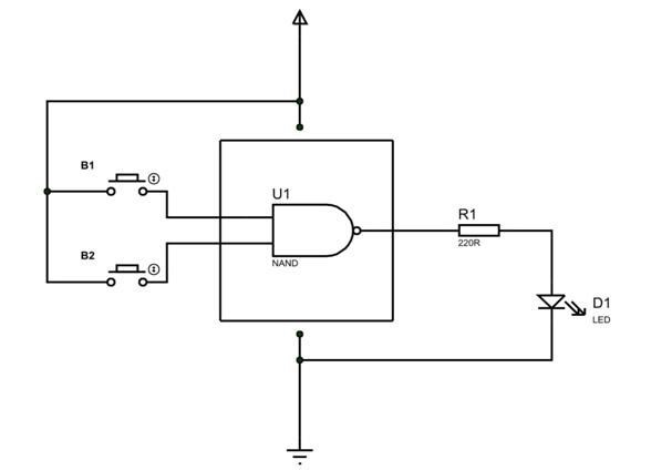
74LS00 Circuit


Two inputs are connected to two buttons, while the output is connected to an LED. The ON and OFF states of this LED reveal the gate's output logic.

Both buttons are open and not pressed under usual conditions. Both of the gate's inputs will be LOW as a result. According to the truth table stated above, when both inputs are LOW, the output will be HIGH. The LED will light on since the output is high.

If one of the buttons is pressed. One of the inputs will be LOW, while the other will be HIGH. According to the truth table, the output will still be HIGH in this situation. The LED will light on since the output is high.

Only when both buttons are pressed will we get a LOW output, which will turn off the LED.

We discovered the truth table for chip NAND gate using these three scenarios. We can satisfy our needs by using all four gates in this manner.

74LS00 Package Dimension

74LS00 Package Dimension

74LS00 Manufacturer

Rochester Electronics ranks as a global leading semiconductor provider. Due to their products' characteristics of high quality and durability, these products are suitable for long-term production and maintenance in the fields of industry, transportation, and high-reliability markets. Their large inventory includes more than 100,000 products and 15 billion units, making them exceed other companies in terms of selection, capabilities, or solutions.

Frequently Asked Questions

74LS00 Manufacturer
74LS00 was used for performing the NAND function. The IC has four NAND gates in it. Each gate can be used separately.
What is the difference between 7400 and 74LS00?
The 74LS00 family improves technically on the 7400 families in two key areas: faster speed and lower power consumption. The only limitation of the 74LS00 family compared to the 7400 families is that the 74LS00 family can only source half as much current.
What is 74LS00 logic gates IC of digital electronics?
The 74LS00 is a TTL (Transistor to Transistor Logic) that uses low-power Shottky transistors to reduce the stored charge and get higher switching speeds than with conventional bipolar transistors. 74LS00 is a 14 pin IC that has four NAND gates each NAND gate has two inputs & one output.
How many 74ls00 NAND gate inputs can be driven by a 74ls00 NAND gate outputs?
The 74xxyy ICs are logic gates of digital electronics. 74LS00 IC has four NAND gates. Also, each gate has two inputs. Hence name QUAD TWO INPUT NAND GATE.
FAQ
74LS00 Manufacturer
74LS00 was used for performing the NAND function. The IC has four NAND gates in it. Each gate can be used separately.
What is the difference between 7400 and 74LS00?
The 74LS00 family improves technically on the 7400 families in two key areas: faster speed and lower power consumption. The only limitation of the 74LS00 family compared to the 7400 families is that the 74LS00 family can only source half as much current.
What is 74LS00 logic gates IC of digital electronics?
The 74LS00 is a TTL (Transistor to Transistor Logic) that uses low-power Shottky transistors to reduce the stored charge and get higher switching speeds than with conventional bipolar transistors. 74LS00 is a 14 pin IC that has four NAND gates each NAND gate has two inputs & one output.
How many 74ls00 NAND gate inputs can be driven by a 74ls00 NAND gate outputs?
The 74xxyy ICs are logic gates of digital electronics. 74LS00 IC has four NAND gates. Also, each gate has two inputs. Hence name QUAD TWO INPUT NAND GATE.

TAGS

Share