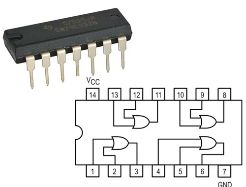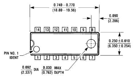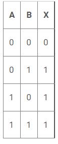
Truth Table of 74LS32
The output of an OR gate should be LOW only if both gate inputs are LOW, as in the truth table. Otherwise, the output should be set to HIGH. As a result, if one or both inputs are HIGH, the OR gate's output will also be HIGH.
We're going to use a 1K resistor to draw both gate inputs to the ground in our OR gate circuit. The inputs are then connected to electricity through a button. The corresponding pin of gate INPUT gets high when the button is pressed. So the truth table of the OR gate can be realized with just two clicks. When one of the buttons is pressed, one of the gate's inputs will be high and the other will be low; the output should be HIGH at this moment. When both buttons are pressed, both inputs are HIGH, and the OR gate's OUTPUT is HIGH at the same moment.
Both INPUTS of OR will be LOW when both buttons are released, and OUTPUT should also be LOW at this moment. As a result, the LED should be turned off only when both buttons are released, according to the truth table. If one or both buttons are pressed, the LED should turn on.

74LS32 Circuit
Because the Integrated Circuit chosen is a positive edge triggering one, these pull-down resistors are required. The circuit could have unforeseen effects if the resistors are neglected. The capacitors in this circuit are used to counteract the bouncing effect of the buttons. Although the capacitors aren't required, they may help the gate function more smoothly.