ATTENTION: Due to increased demand and order volume, processing time may take an additional 1-3 business days.
HomeCommunitySubjectA1302 Hall Effect Sensor: Allegro A1302, Datasheet, A1302 Arduino

A1302 Hall Effect Sensor: Allegro A1302, Datasheet, A1302 Arduino

Magnetic Sensors - Linear, Compass (ICs) SENSOR, HALL EFFECT, LINEAR, 3SIP The A1301 and A1302 are continuous-time, ratiometric, linear Hall-effect sensor ICs.

4190

Nov 15, 2021

Gene Juliet

Hall Effect Sensor with Arduino - A1302

Magnetic Sensors - Linear, Compass (ICs) SENSOR, HALL EFFECT, LINEAR, 3SIP

The A1301 and A1302 are continuous-time, ratiometric, linear Hall-effect sensor ICs. This article will unlock more details about A1302. There is a huge range of Semiconductors, Capacitors, Resistors and ICs in stock. Welcome RFQ!
 

A1302KUA-T

32600In Stock
Min.: 1 Mult.: 1
Price not displayed? Not available to buy online? Please send an RFQ, and we will respond immediately.
Quick Links

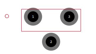
A1302 Pinout

A1302 Pinout


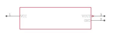
Symbol pin Description
VCC 1 Connects power supply to the chip
VOUT 3 Output from circuit
GND 2 Ground

A1302 CAD Model

A1302 Symbol


A1302 Footprint

A1302 Description

The A1302 is a continuous-time, ratiometric, linear Hall-effect sensor IC. They are optimized to accurately provide a voltage output that is proportional to an applied magnetic field. These devices have a quiescent output voltage that is 50% of the supply voltage. 

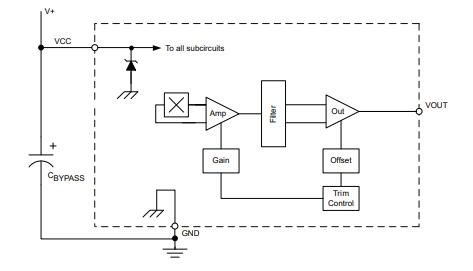
The Hall-effect integrated circuit included in each device includes a Hall circuit, a linear amplifier, and a CMOS Class A output structure. Integrating the Hall circuit and the amplifier on a single chip minimizes many of the problems normally associated with low voltage level analogue signals. High precision in output levels is obtained by internal gain and offset trim adjustments made at the end-of-line during the manufacturing process.

A1302 Feature

▪ Low-noise output 

▪ Fast power-on time 

▪ Ratiometric rail-to-rail output 

▪ 4.5 to 6.0 V operation 

▪ Solid-state reliability 

▪ Factory-programmed at end-of-line for optimum performance 

▪ Robust ESD performance

A1302 Funtional Block Diagram

A1302 Functional Block Diagram

Specifications

Allegro MicroSystems A1302KUA-T technical specifications, attributes, parameters and parts with similar specifications to Allegro MicroSystems A1302KUA-T.

A1302KUA-T Tech Specifications

Allegro MicroSystems A1302KUA-T technical specifications, attributes, parameters and parts with similar specifications to Allegro MicroSystems A1302KUA-T.

Product Attribute Attribute Value
Factory Lead Time16 Weeks
Contact PlatingTin
MountThrough Hole
Mounting TypeThrough Hole
Package / Case3-SSIP
Number of Pins3Pins
Operating Temperature-40°C~125°C TA
PackagingBulk
Published2007
JESD-609 Codee3
Pbfree Codeyes
Part StatusObsolete
Product Attribute Attribute Value
Moisture Sensitivity Level (MSL)1 (Unlimited)
Number of Terminations3Terminations
Resistance2Ohm
Additional FeatureMAGNETIC SENSITIVITY
Voltage - Supply4.5V~6V
Output TypeAnalog Voltage
Max Output Current10mA
Operating Supply Voltage5V
Termination TypeSOLDER
Operating Supply Current11mA
Output Current10mA
Max Supply Current11mA
Product Attribute Attribute Value
Linearity2.5 %
AxisSingle
Output Range0.25-4.65V
Input ModeUNIPOLAR
Number of Axes1Axe
Height3.02mm
Length4.09mm
Width1.52mm
REACH SVHCNo SVHC
Radiation HardeningNo
RoHS StatusROHS3 Compliant
Lead FreeLead Free
0 Products View Similar

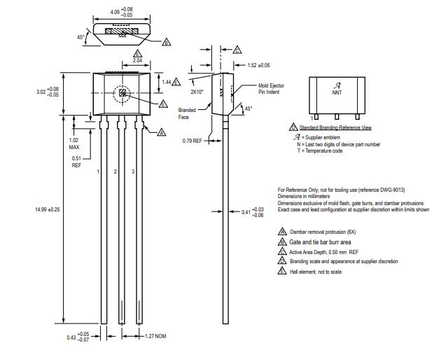
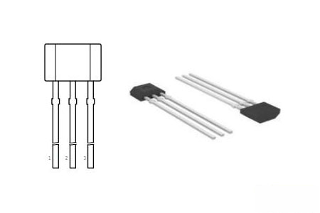
A1302 Package

A1302 Package

A1302 Manufacturer

Allegro MicroSystems, LLC is a leader in developing, manufacturing and marketing high-performance semiconductors. Allegro's innovative solutions serve high-growth applications within the automotive market, with an additional focus on office automation, industrial, and consumer/communications solutions. Allegro is headquartered in Worcester, Massachusetts (USA) with design, applications, and sales support centres located worldwide.

Datasheet PDF

A1302KUA-T Documents

Download datasheets and manufacturer documentation for A1302KUA-T

Datasheets
A1301,02
PCN Part Status Change
NRND Notice 28/Dec/2015
PCN Obsolescence/ EOL
A130YYY 22/Sep/2016

Frequently Asked Questions

What is A1302?
The A1302 is a continuous-time, ratiometric, linear Hall-effect sensor IC. They are optimized to accurately provide a voltage output that is proportional to an applied magnetic field. These devices have a quiescent output voltage that is 50% of the supply voltage. The Hall-effect integrated circuit included in each device includes a Hall circuit, a linear amplifier, and a CMOS Class A output structure. Integrating the Hall circuit and the amplifier on a single chip minimizes many of the problems normally associated with low voltage level analogue signals. High precision in output levels is obtained by internal gain and offset trim adjustments made at the end-of-line during the manufacturing process.
What does a Hall effect sensor do?
The Hall-effect sensor is able to distinguish between the positive and negative charges moving in the opposite direction. The magnetic field detected by the hall-effect sensor is converted to a suitable analogue or digital signal that can be read by the electronic system, usually a motor control system.
What are the advantages and disadvantages of using Hall effect sensors?
When packed immune to dust, air, water whereas capacitive sensor may get triggered by dust. It can measure zero speed. Non-contact operation so there is no wear and friction, hence the unlimited number of operating cycles. Highly repeatable operation.
What are some applications for the Hall effect sensor?
For examples. Some of the examples for the application of Hall Effect sensors are the current transformers, Position sensing, Galaxy S4 Accessories, Keyboard switch, computers, Proximity sensing, speed detection, current sensing applications, tachometers, anti-lock braking systems, magnetometers, DC motors, disk drives etc ...
FAQ
What is A1302?
The A1302 is a continuous-time, ratiometric, linear Hall-effect sensor IC. They are optimized to accurately provide a voltage output that is proportional to an applied magnetic field. These devices have a quiescent output voltage that is 50% of the supply voltage. The Hall-effect integrated circuit included in each device includes a Hall circuit, a linear amplifier, and a CMOS Class A output structure. Integrating the Hall circuit and the amplifier on a single chip minimizes many of the problems normally associated with low voltage level analogue signals. High precision in output levels is obtained by internal gain and offset trim adjustments made at the end-of-line during the manufacturing process.
What does a Hall effect sensor do?
The Hall-effect sensor is able to distinguish between the positive and negative charges moving in the opposite direction. The magnetic field detected by the hall-effect sensor is converted to a suitable analogue or digital signal that can be read by the electronic system, usually a motor control system.
What are the advantages and disadvantages of using Hall effect sensors?
When packed immune to dust, air, water whereas capacitive sensor may get triggered by dust. It can measure zero speed. Non-contact operation so there is no wear and friction, hence the unlimited number of operating cycles. Highly repeatable operation.
What are some applications for the Hall effect sensor?
For examples. Some of the examples for the application of Hall Effect sensors are the current transformers, Position sensing, Galaxy S4 Accessories, Keyboard switch, computers, Proximity sensing, speed detection, current sensing applications, tachometers, anti-lock braking systems, magnetometers, DC motors, disk drives etc ...

TAGS

Share