ATTENTION: Due to increased demand and order volume, processing time may take an additional 1-3 business days.
HomeCommunitySubjectA3144 Hall Effect Sensor: Datasheet, Circuit and Pinout

A3144 Hall Effect Sensor: Datasheet, Circuit and Pinout

Unclassified A3144 is a small, versatile, linear unipolar hall-effect sensor that acts as a magnetic switch. This article mainly covers datasheet, pinout, applications, working, and other details about the A3144 hall effect sensor.

7252

Oct 18, 2021

Deirdre Emma

Hall Effect Sensor A3144 Magnetic Switch || Circuit Diagram & Working


Unclassified

A3144 is a small, versatile, linear unipolar hall-effect sensor that acts as a magnetic switch. This article mainly covers datasheet, pinout, applications, working, and other details about the A3144 hall effect sensor.


A3144EU

285In Stock
Min.: 1 Mult.: 1
Price not displayed? Not available to buy online? Please send an RFQ, and we will respond immediately.
Quick Links

Overview of A3144 Hall Effect Sensor

A3144 is a small, versatile, linear unipolar hall-effect sensor that acts as a magnetic switch. Because of the semiconductor type case and lack of glass encapsulation, this Hall Effect sensor is similar to a switch but is more sensitive to magnetic flux and ideal for severe environments. When one pole of a magnet comes close to this type of unipolar Hall Effect sensor, it changes its state. This is appropriate for commercial, consumer, and industrial use.

A3144 Hall Effect Sensor Pinout

A3144 hall effect sensor consists of three pins which are shown in the following diagram.

The first pin is the power pin, which is used to power this sensor. On this sensor, 5V dc voltages are employed for power. The ground pin, on the other hand, is utilized to provide ground to this sensor. The digital output pin, on the other hand, is connected to an interface controller such as a microcontroller or an Arduino. However, between pins 1 and 3, a 10k ohm pull-up resistor is required to keep the output high when there is no magnetic field. A capacitor with a value of 0.1F is also required between pins 2 and 3 for filtering the digital output because noise may be linked with it.

A3144 Pinout


No Pin Name Description
1 '+5V (Vcc) Used to power the   hall sensor, typically +5V is used
2 Ground Connect to the ground   of the circuit
3 Output This pin goes high if a magnet is detected. The output voltage is equal to the Operating voltage.

A3144 Hall Sensor Specifications and Features

  • Power Consumption of 3.5mA at VCC = 5V for Energy Efficiency

  • Miniature Construction

  • Single Current Sourcing Output

  • Linear Output for Circuit Design Flexibility

  • Low Noise Output Virtually Eliminates the Need for Filtering

  • A Stable and Accurate Output

  • Temperature Range of -40°C to +85°C

  • Responds to either Positive or Negative Gauss

Alternatives for A3144 Hall Effect Sensor

A3141, A3142, A3143, US1881, OH090U


A3144 Hall Effect Sensor Applications

  • Used to detect magnets (objects) in automation systems

  • Used in a magnetic door alarm system

  • Measure speed in automobiles

  • Detect the pole of magnets in BLDC motors


Working Principle of A3144 Hall Effect Sensor

Every A3144 Hall Effect Sensor is made up of a material with a magnetic field. However, the magnetic field's charges are not active. When voltages are added to the input pins of the device, these changes become active. When a beam of charged particles passes through this magnetic field, a force is applied to the particles, and the beam is reflected in its original path. This beam is a conductor that carries current.

As a result of this entire process, two planes are formed: one with a magnetic field and the other with a deflected back beam or a current-carrying conductor. As a result, one plane has a positive charge while the other has a negative charge. Hall Effect voltages are the voltages that exist between these two planes. The gap between these two planes will be stopped if the force between the current carry conductor and the magnetic field is equal. If there is no current change, the flux density is measured by the hall voltages.
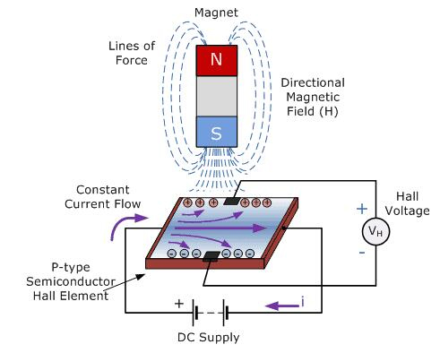
A3144 Working Principle

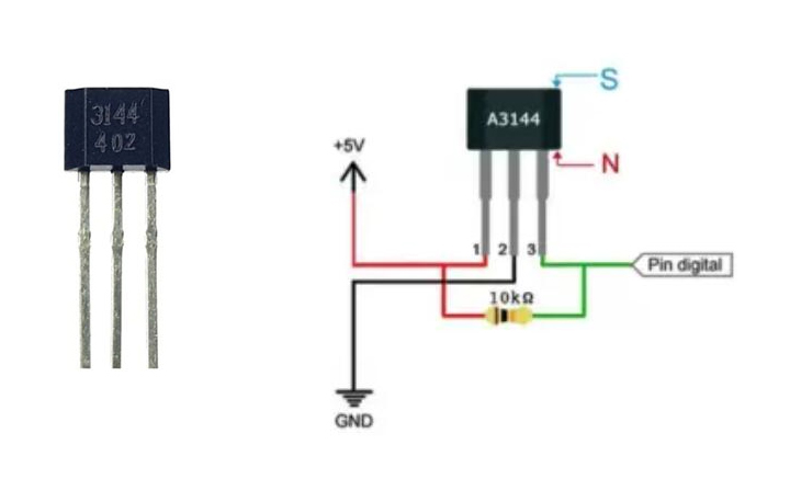
Where to Use A3144 Hall Effect Sensor

hall-effect sensor, as the name implies, works on the hall-effect principle and is used to detect magnets. One pole can be detected on each side of the sensor. Because it uses transistor logic, it can be easily interfaced with a microcontroller.

So, if you need a sensor to detect magnets to measure the speed of a moving object or simply to identify objects, this sensor could be the right fit for your project.

How to Use A3144 Hall Effect Sensor

There are two types of hall-effect sensors: one that outputs an analog signal and the other that outputs a digital signal. The A3144 is a digital output hall sensor, which means that if it senses a magnet, the output will fall low, however, if it detects nothing, the output will stay high. A pull-up resistor, as illustrated below, is also required to maintain the output high when no magnet is detected.

A3144 Circuit

In the above circuit diagram, the resistor R1 (10K) is used as a pull-up resistor and the capacitor C1 (0.1uF) is used to filter any noise that might be coupled with the digital output.

Dimensions of A3144 Hall Effect Sensor

 Dimensions of A3144 Hall Effect Sensor

Manufacturer of A3144 Hall Effect Sensor

As a leading company in the development, manufacture, and market of high-performance semiconductors, Allegro MicroSystems, LLC provides high-growth applications for the automotive market and also stays focused on consumer/communications, automation, and industrial solutions. Headquartered in Worcester, Massachusetts (USA) Allegro locates its design, applications, and sales support centers worldwide.

Frequently Asked Questions

What is the use of A3144?
A3144 is a digital output hall sensor, meaning if it detects a magnet the output will go low else the output will remain high. It is also mandatory to use a pull-up resistor as shown below to keep the output high when no magnet is detected.
How does A3144 work?
The A3144 is an integrated Hall Effect non-latching sensor. Holding a magnet near the sensor will cause the output pin to toggle. This makes for a robust presence sensor.A3144 is a digital output hall sensor, meaning if it detects a magnet the output will go low else the output will remain high.
Is CS3144 the same as A3144?
It is a type of Hall element, the specific parameters may be slightly different, and the pin definitions are the same.
FAQ
What is the use of A3144?
A3144 is a digital output hall sensor, meaning if it detects a magnet the output will go low else the output will remain high. It is also mandatory to use a pull-up resistor as shown below to keep the output high when no magnet is detected.
How does A3144 work?
The A3144 is an integrated Hall Effect non-latching sensor. Holding a magnet near the sensor will cause the output pin to toggle. This makes for a robust presence sensor.A3144 is a digital output hall sensor, meaning if it detects a magnet the output will go low else the output will remain high.
Is CS3144 the same as A3144?
It is a type of Hall element, the specific parameters may be slightly different, and the pin definitions are the same.

TAGS

Share