ATTENTION: Due to increased demand and order volume, processing time may take an additional 1-3 business days.
HomeCommunitySubjectACS712 Current Sensor: Pinout, Datasheet and Circuit

ACS712 Current Sensor: Pinout, Datasheet and Circuit

ALLEGRO MICROSYSTEMS - ACS712ELCTR-20A-T - Current Sensor, Voltage Isolation, 10 mA, 80 kHz, SOIC, 8 Pins, 4.5 V, 5.5 V

287

Jul 3, 2021

Ben Amelia

Using the ACS712 Hall Effect Current Sensor Module (part 1)


ALLEGRO MICROSYSTEMS - ACS712ELCTR-20A-T - Current Sensor, Voltage Isolation, 10 mA, 80 kHz, SOIC, 8 Pins, 4.5 V, 5.5 V

ACS712 is a fully integrated, hall-effect-based linear current sensor. This blog mainly covers pinout, cad model, circuit and other information about ACS712.
ACS712ELCTR-20A-T

30000In Stock
Min.: 1 Mult.: 1
Quantity Unit Price Ext. Price
1+ $2.81837$2.82
10+ $2.65884$26.59
100+ $2.50834$250.83
500+ $2.36636$1183.18
1000+ $2.23242$2232.42
Unit Price:$2.81837
Subtotal: $2.82
Looking for a better price? Want a lower wholesale price? Please send an RFQ, and we will respond immediately.
Quick Links

ACS712 Description

The Allegro™ ACS712 provides economical and precise solutions for AC or DC current sensing in industrial, commercial, and communications systems. The device package allows for easy implementation by the customer. Typical applications include motor control, load detection and management, switchmode power supplies, and overcurrent fault protection. The device is not intended for automotive applications.

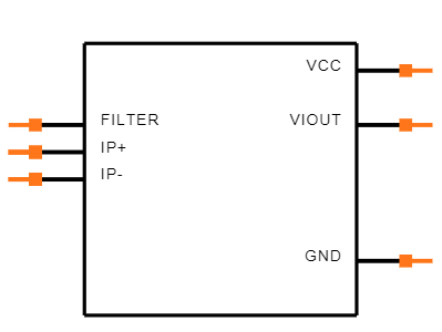
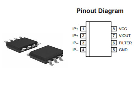
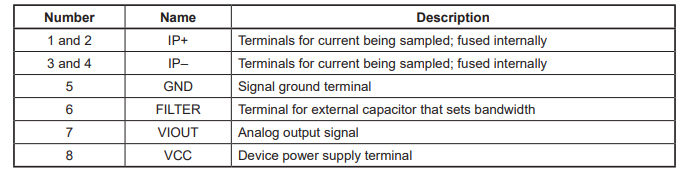
ACS712 Pinout

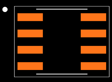
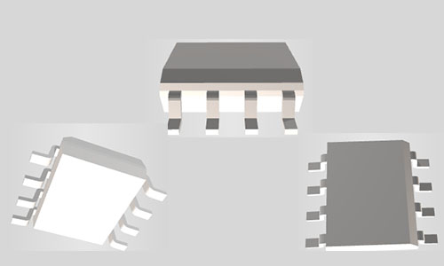
ACS712 CAD Model

Symbol


Footprint


3D Model

Specifications

Allegro MicroSystems ACS712ELCTR-20A-T technical specifications, attributes, parameters and parts with similar specifications to Allegro MicroSystems ACS712ELCTR-20A-T.

ACS712ELCTR-20A-T Tech Specifications

Allegro MicroSystems ACS712ELCTR-20A-T technical specifications, attributes, parameters and parts with similar specifications to Allegro MicroSystems ACS712ELCTR-20A-T.

Product Attribute Attribute Value
Factory Lead Time18 Weeks
Mounting TypeSurface Mount
Package / Case8-SOIC (0.154, 3.90mm Width)
Surface MountYES
Number of Pins8Pins
Current Sensing20A
Operating Temperature-40°C~85°C
PackagingTape & Reel (TR)
Published2007
JESD-609 Codee3
Pbfree Codeyes
Part StatusNot For New Designs
Moisture Sensitivity Level (MSL)2 (1 Year)
Number of Terminations8Terminations
TerminationSMD/SMT
Product Attribute Attribute Value
Terminal FinishMatte Tin (Sn)
Voltage - Supply5V
Terminal PositionDUAL
Terminal FormGULL WING
Peak Reflow Temperature (Cel)260
Number of Functions1Function
Supply Voltage5V
FrequencyDC~80kHz
Time@Peak Reflow Temperature-Max (s)40
OutputRatiometric, Voltage
Pin Count8
Operating Supply Voltage5V
Number of Channels1Channel
Analog IC - Other TypeANALOG CIRCUIT
PolarizationBidirectional
Product Attribute Attribute Value
Output Current10mA
Max Supply Current13mA
Quiescent Current10mA
Response Time5μs
Sensor TypeHall Effect, Open Loop
Linearity±1.5%
For MeasuringAC/DC
Sensitivity (mV/A)100 mV/A
Height1.5mm
Length4.9mm
Width3.9mm
REACH SVHCNo SVHC
Radiation HardeningNo
RoHS StatusROHS3 Compliant
Lead FreeLead Free
0 Products View Similar

ACS712 Features and Advantages

  • Low-noise analog signal path

  • Device bandwidth is set via the new FILTER pin

  • 5 µs output rise time in response to step input current

  • 80 kHz bandwidth ▪ Total output error 1.5% at TA= 25°C

  • Small footprint, low-profile SOIC8 package

  • 1.2 mΩ internal conductor resistance

  • 2.1 kVRMS minimum isolation voltage from pins 1-4 to pins 5-8

  • 5.0 V, single supply operation

  • 66 to 185 mV/A output sensitivity

  • Output voltage proportional to AC or DC currents

  • Factory-trimmed for accuracy ▪ Extremely stable output offset voltage

  • Nearly zero magnetic hysteresis

  • Ratiometric output from supply voltage

ACS712 Functional Block Diagram

ACS712 Alternatives

ACS759, WCS1700, KG190, ACS715


ACS712 Applications

  • Motor speed control in motor control circuits.

  • Electrical load detection and management.

  • Switched-mode power supplies (SMPS)

  • Protection for over-current.

Where to use ACS712 Module

These ACS712 module can measure current AC or DC current ranging from +5A to -5A, +20A to -20A and +30A to -30A. You have to select the right range for your project since you have to trade off accuracy for higher range modules. This modules outputs Analog voltage (0-5V) based on the current flowing through the wire; hence it is very easy to interface this module with any microcontroller. So if you are looking for a module to measure current using a microcontroller for you project then this module might be the right choice for you.

How to use ACS712

The ACS712 module has two phoenix terminal connectors (green colour ones) with mounting screws as shown above. These are the terminals through which the wire has to be passed. In our case I am measuring the current drawn by the motor so the wires that is going to the load (motor) is passed through the ACS 712 Module. Make sure the module is connected in series with the load and be extra cautious to avoid shorts.

On the other side we have three pins. The Vcc is connected to +5V to power the module and the ground is connected to the ground of the MCU (system). Then the analog voltage given out by the ACS712 module is read using any analog pin on the Microcontroller.


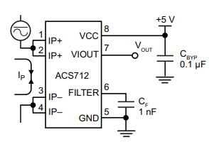
ACS712 Circuit

ACS712 Programming

By default when no current is flowing through the module terminals the output voltage will be +2.5V (Vcc/2), when the current flows in one direction the value will increase from 2.5V and when it flows in other direction the values will decrease from 2.5V. This way the module enables us to measure both AC current and DC current. Let us assume that the microcontroller you are using has a 10-bit ADC and operates at 5V with a reference voltage of 5V for ADC conversion in that case the microcontroller will read the values of ADC from 0 to 1024. Then you can use the formulae below to calculate the Output Voltage from ADC values.


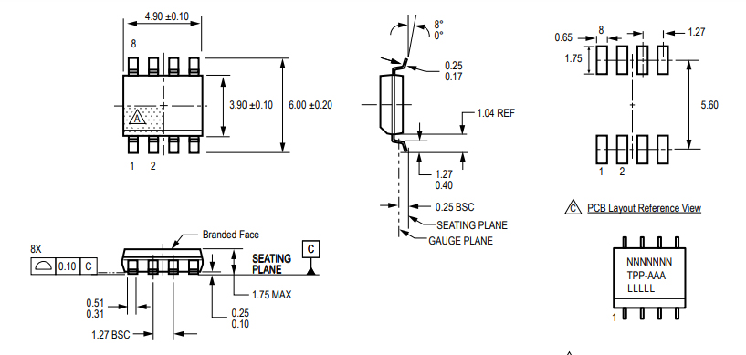
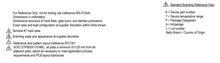
ACS712 Package

ACS712 Manufacturer

Allegro MicroSystems, LLC is a leader in developing, manufacturing and marketing high-performance semiconductors. Allegro's innovative solutions serve high-growth applications within the automotive market, with additional focus on office automation, industrial, and consumer/communications solutions. Allegro is headquartered in Worcester, Massachusetts (USA) with design, applications, and sales support centers located worldwide.

Datasheet PDF

Download datasheets and manufacturer documentation for Allegro MicroSystems ACS712ELCTR-20A-T.

ACS712ELCTR-20A-T Documents

Download datasheets and manufacturer documentation for ACS712ELCTR-20A-T

Datasheets
ACS712
PCN Part Status Change
Mult Devices 14/Jun/2017

Frequently Asked Questions

How do I connect an ACS712 to Arduino?
The ACS712 Current Sensor is a cool little device for making current measurements. Better, its really easy to use with an Arduino. In this sample project, I’ll show you just how easy it is to connect up, program and put to immediate use.An ACS712 Current Sensor Module – I chose to use the 5 amp version. There are 20 amp and 30 amp versions also available. If you’re not all that familiar with this module, you can read my online user manual. If you don’t have one of these modules and think that you may want one, you can try these links. It will only set you back a few dollars.
Where can I find ACS712 Arduino code examples?
The ACS712 is a handy little current sensor from Allegro MicroSystems for low to moderate current sensing applications. SparkFun offers two flavors of breakout board, one with just the sensor and another with an on-board amplifier to increase the sensitivity. The ACS712 sensor uses a Hall effect sensor to output a voltage relative to the current flowing through the IP+ and IP- pins. The advantage of using a Hall effect sensor is that the circuit being sensed and the circuit reading the sensor are electrically isolated. This means that, although your Arduino is running on 5V, the sensed circuit can be operating at higher DC or AC voltages!
How do I measure an ACS712 DC current?
In this tutorial i am going to measure DC current using Acs712 Hall Effect-Based Linear Current Sensor. I am going to measure current precisely. I have gone through various blogs on internet and all of them are measuring current with formulas that are not precise. I will be defining the best method and precise formula generation for measuring the current. I will define each and every step thoroughly and deeply with logic. Project Code is open source and you can download and modify it according to your needs. For this post/tutorial/project i am going to measure only dc current.
How do I use an ACS712 with Raspberry Pi?
The ADC Pi can also be used with the ACS712 range of current sensors to read AC or DC current. The code sample from our GitHub page will allow you to read the 30 amp version of the ACS712 sensor and display the current flow which is updated every second.
How do I connect the the ACS712 to the ESP8266?
Because of the very cheap ACS712 Current Sensor Board modules available all over the place, I really think that everybody heard about ACS712 sensor from Allegro MicroSystems.As I was asked if “Can be used as a current sensor module for our ESP8266 Projects without too much hustle?”, I ordered few of them and let’s explore them for the answer.
FAQ
How do I connect an ACS712 to Arduino?
The ACS712 Current Sensor is a cool little device for making current measurements. Better, its really easy to use with an Arduino. In this sample project, I’ll show you just how easy it is to connect up, program and put to immediate use.An ACS712 Current Sensor Module – I chose to use the 5 amp version. There are 20 amp and 30 amp versions also available. If you’re not all that familiar with this module, you can read my online user manual. If you don’t have one of these modules and think that you may want one, you can try these links. It will only set you back a few dollars.
Where can I find ACS712 Arduino code examples?
The ACS712 is a handy little current sensor from Allegro MicroSystems for low to moderate current sensing applications. SparkFun offers two flavors of breakout board, one with just the sensor and another with an on-board amplifier to increase the sensitivity. The ACS712 sensor uses a Hall effect sensor to output a voltage relative to the current flowing through the IP+ and IP- pins. The advantage of using a Hall effect sensor is that the circuit being sensed and the circuit reading the sensor are electrically isolated. This means that, although your Arduino is running on 5V, the sensed circuit can be operating at higher DC or AC voltages!
How do I measure an ACS712 DC current?
In this tutorial i am going to measure DC current using Acs712 Hall Effect-Based Linear Current Sensor. I am going to measure current precisely. I have gone through various blogs on internet and all of them are measuring current with formulas that are not precise. I will be defining the best method and precise formula generation for measuring the current. I will define each and every step thoroughly and deeply with logic. Project Code is open source and you can download and modify it according to your needs. For this post/tutorial/project i am going to measure only dc current.
How do I use an ACS712 with Raspberry Pi?
The ADC Pi can also be used with the ACS712 range of current sensors to read AC or DC current. The code sample from our GitHub page will allow you to read the 30 amp version of the ACS712 sensor and display the current flow which is updated every second.
How do I connect the the ACS712 to the ESP8266?
Because of the very cheap ACS712 Current Sensor Board modules available all over the place, I really think that everybody heard about ACS712 sensor from Allegro MicroSystems.As I was asked if “Can be used as a current sensor module for our ESP8266 Projects without too much hustle?”, I ordered few of them and let’s explore them for the answer.

TAGS

Share