ATTENTION: Due to increased demand and order volume, processing time may take an additional 1-3 business days.
HomeCommunitySubjectAD260BND-1 Digital Isolators: Pinout, Specification, Datasheet

AD260BND-1 Digital Isolators: Pinout, Specification, Datasheet

DGTL ISO 3.5KV GEN PURP 22DIP The AD260BND-1 is designed using Analog Devices' new IsoLogic circuit architecture to isolate five digital control signals to/ from a microcontroller and its related field I/O components.

357

Feb 18, 2021

Amelia

DGTL ISO 3.5KV GEN PURP 22DIP

The AD260BND-1 is designed using Analog Devices' new IsoLogic circuit architecture to isolate five digital control signals to/ from a microcontroller and its related field I/O components. Six models allow all I/O combinations from five input lines to five output lines, including combinations in between. Every AD260 effectively replaces up to five optoisolators while also providing the 1.5W transformer for a 3.5 kV isolated dc-dc power supply circuit.
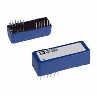
AD260BND-1

47In Stock
Min.: 1 Mult.: 1
Price not displayed? Not available to buy online? Please send an RFQ, and we will respond immediately.
Quick Links

AD260BND-1 Description

The AD260BND-1 is designed using Analog Devices new IsoLogic circuit architecture to isolate five digital control signals to/ from a microcontroller and its related field I/O components. Six models allow all I/O combinations from five input lines to five output lines, including combinations in between. Every AD260 effectively replaces up to five optoisolators while also providing the 1.5 W transformer for a 3.5 kV isolated dc-dc power supply circuit. 
Each line of the AD260 has a bandwidth of 20 MHz (min) with a propagation delay of only 14 ns, which allows for extremely fast data transmission. Output waveform symmetry is maintained to within ±1 ns of the input so the AD260 can be used to accurately isolate time-based PWM signals. 

All field or system output pins of the AD260 can be set to a high resistance three-state level by use of the two enable pins. A field output three-stated offers a convenient method of presetting logic levels at power-up by use of pull-up/down resistors. System side outputs being three-stated allows for easy multiplexing of multiple AD260s.

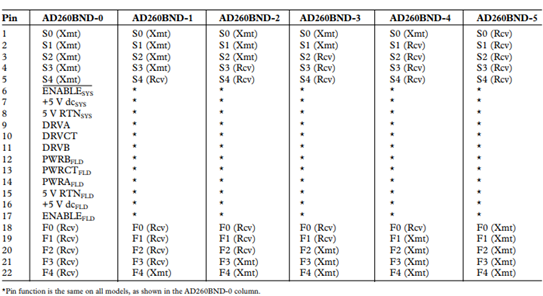
AD260BND-1 Pinout

AD260BND-1 CAD Model

AD260BND-1 Feature

IsoLogic™ Circuit Architecture

Isolation Test Voltage: To 3.5kV rms

Five Isolated Logic Lines: Available in Six I/O Configurations

Logic Signal Bandwidth: 20 MHz (Min), 40 mbps (NRZ)

Isolated Power Transformer: 37 V p-p, 1.5 W Max

CMV Transient Immunity: 10 kV/ms Min

Waveform Edge Transmission Symmetry: 61ns

Field and System Output Enable/Three-State Functions

Performance Rated Over –258C to +858C

UL1950, IEC950, EN60950 Certification, Pending


AD260BND-1 Advantage

Six Isolated Logic Line I/O Configurations Available:

The AD260 is available in six pin-compatible versions of I/O configurations to meet a wide variety of requirements.

Wide Bandwidth with Minimal Edge Error:

The AD260 with IsoLogic affords extremely fast isolation of logic signals due to its 20 MHz bandwidth and 14 ns propagation delay. It maintains a waveform input-to-output edge transition error of typically less than ±1 ns (total) for positive vs. negative transition.

3.5 kV rms Test Voltage Isolation Rating:

The AD260 B Grade is rated to operate at 1.25 kV rms and is 100% production tested at 3.5 kV rms, using a standard ADI test method.

High Transient Immunity:

The AD260 rejects common-mode transients slewing at up to 10 kV/µs without false triggering or damage to the device.


Specifications

Analog Devices Inc. AD260BND-1 technical specifications, attributes, parameters and parts with similar specifications to Analog Devices Inc. AD260BND-1.

AD260BND-1 Tech Specifications

Analog Devices Inc. AD260BND-1 technical specifications, attributes, parameters and parts with similar specifications to Analog Devices Inc. AD260BND-1.

Product Attribute Attribute Value
Lifecycle StatusOBSOLETE (Last Updated: 1 month ago)
Contact PlatingLead, Tin
MountThrough Hole
Mounting TypeThrough Hole
Package / Case22-DIP Module
Number of Pins22Pins
Operating Temperature-25°C~85°C
PackagingTube
SeriesIsoLogic™
Pbfree Codeno
Part StatusObsolete
Moisture Sensitivity Level (MSL)1 (Unlimited)
Product Attribute Attribute Value
Number of Terminations22Terminations
ECCN CodeEAR99
TypeGeneral Purpose
Voltage - Supply4V~5.75V
Terminal PositionQUAD
Number of Functions1Function
Supply Voltage5V
Base Part NumberAD260
Pin Count22
Voltage - Isolation3500Vrms
Operating Supply Voltage5V
Number of Channels5Channels
Product Attribute Attribute Value
Operating Supply Current4mA
Propagation Delay25 ns
Channel TypeUnidirectional
Propagation Delay tpLH / tpHL (Max)25ns, 25ns
Common Mode Transient Immunity (Min)10kV/μs
Supply Voltage1-Nom5V
Inputs - Side 1/Side 21/4
Isolated PowerYes
Pulse Width Distortion (PWD)25 ns
Radiation HardeningNo
RoHS StatusNon-RoHS Compliant
Lead FreeContains Lead
0 Products View Similar

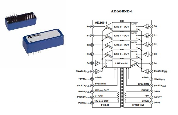
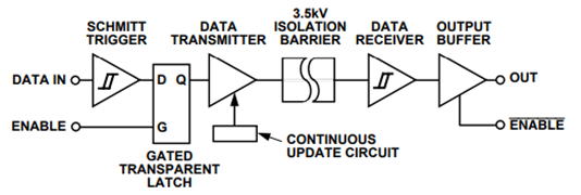
AD260BND-1 Block Diagram

AD260BND-1 Application

PLC/DCS Analog Input and Output Cards

Communications Bus Isolation

General Data Acquisition Applications

IGBT Motor Drive Controls

High Speed Digital I/O Ports

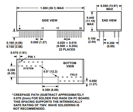
AD260BND-1 Dimension

AD260BND-1 Manufacturer

Analog Devices (NASDAQ: ADI) is a world leader in the design, manufacture, and marketing of a broad portfolio of high performance analog, mixed-signal, and digital signal processing (DSP) integrated circuits (ICs) used in virtually all types of electronic equipment. Since our inception in 1965, we have focused on solving the engineering challenges associated with signal processing in electronic equipment. Used by over 100,000 customers worldwide, our signal processing products play a fundamental role in converting, conditioning, and processing real-world phenomena such as temperature, pressure, sound, light, speed, and motion into electrical signals to be used in a wide array of electronic devices.


Datasheet PDF

Download datasheets and manufacturer documentation for Analog Devices Inc. AD260BND-1.

AD260BND-1 Documents

Download datasheets and manufacturer documentation for AD260BND-1

PCN Obsolescence/ EOL
Mult Dev EOL 9/Oct/2017
PCN Design/Specification
Hard Cap Encapsulation 25/Jul/2013
ConflictMineralStatement
Analog-Devices-company-33.pdf

Frequently Asked Questions

1.What does a single enable pin on either side of the barrier do?
A single enable pin on either side of the barrier causes all outputs on that side to go three-state and all inputs (driven pins) to ignore their inputs and retain their last known state.
2.Why there are six AD260 part configurations?
The five unidirectional logic lines have six possible combinations of “ins” and “outs”, or transmitter/ receiver pairs; hence there are six AD260 part configurations.
3.What does each logic line barrier driver require?
Each logic line barrier driver requires about 160µA per MHz and each receiver 40 µA per MHz plus, of course, 4 mA total idle current (each side).
4.Why the maximum square-wave frequency of operation is 20MHz?
The total capacitance spanning the isolation barrier is about 25 ns. Therefore the maximum square-wave frequency of operation is 20 MHz.
FAQ
1.What does a single enable pin on either side of the barrier do?
A single enable pin on either side of the barrier causes all outputs on that side to go three-state and all inputs (driven pins) to ignore their inputs and retain their last known state.
2.Why there are six AD260 part configurations?
The five unidirectional logic lines have six possible combinations of “ins” and “outs”, or transmitter/ receiver pairs; hence there are six AD260 part configurations.
3.What does each logic line barrier driver require?
Each logic line barrier driver requires about 160µA per MHz and each receiver 40 µA per MHz plus, of course, 4 mA total idle current (each side).
4.Why the maximum square-wave frequency of operation is 20MHz?
The total capacitance spanning the isolation barrier is about 25 ns. Therefore the maximum square-wave frequency of operation is 20 MHz.

TAGS

Share