ADC interfacing | introduction | ADC0808/0809
IC ADC 8BIT SAR 28DIP
The ADC0808 IC is a commonly used ADC module. This article will unlock more details about ADC0808.

IC ADC 8BIT SAR 28DIP The ADC0808 IC is a commonly used ADC module. This article will unlock more details about ADC0808.
407
Sep 23, 2021
Audrey Orlando
ADC interfacing | introduction | ADC0808/0809
IC ADC 8BIT SAR 28DIP
The ADC0808 IC is a commonly used ADC module. This article will unlock more details about ADC0808.
ADC0808CCN

ADC0808 Pinout
| Pin Number | Pin Name | Description |
| 1 to 5, 27, 28 | Analog Channel 1 to 5 | These 7 pins are the input pins for Analog voltage(sensor) |
| 6 | START | This is an input pin that is made high to start conversion |
| 7 | End of Conversion (EOC) | This is an output pin that goes high once the conversion is over |
| 8,14,15,18,19,20,21 | Output (2-1 to 2-7) | Output digital pins which give the result of the ADC conversion |
| 9 | OUTEN | Has to be made high to get output on output pins |
| 10 | CLOCK | Has to be given clock signals (0V-5V) 20Mhz approx. |
| 11 | Vcc | Powers the IC typically with 5V |
| 12 | V ref(+) | Reference voltage pin, typically +5V is used normally |
| 13 | Ground | Connect to the ground of the circuit |
| 16 | Vref(-) | Vref is connected to the ground normally |
| 22 | Address Latch Enable(ALE) | This pin is should be temporarily made high to select the ADC channel |
| 23,24,25 | ADD A, ADD B, ADD C | These three pins are used to select the channel |
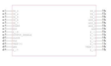
ADC0808 Symbol

ADC0808 Footprint
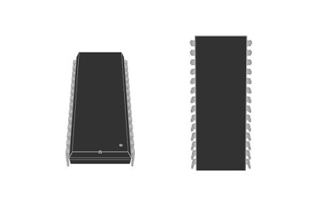
ADC0808 3D Model
The ADC0808 IC is a typical ADC module for projects that require an external ADC. It's a 28-pin 8-bit ADC module with eight channels. It can measure up to eight ADC values from 0 to 5V, with a precision of 19.53mV when the voltage reference (Vref –pin 9) is +5V. (Step size).
Texas Instruments ADC0808CCN technical specifications, attributes, parameters and parts with similar specifications to Texas Instruments ADC0808CCN.
Texas Instruments ADC0808CCN technical specifications, attributes, parameters and parts with similar specifications to Texas Instruments ADC0808CCN.
| Product Attribute | Attribute Value | |
|---|---|---|
| Mount | Through Hole | |
| Mounting Type | Through Hole | |
| Package / Case | 28-DIP (0.600, 15.24mm) | |
| Number of Pins | 28Pins | |
| Number of Elements | 1 Element | |
| Operating Temperature | -40°C~85°C | |
| Packaging | Tube | |
| JESD-609 Code | e0 | |
| Part Status | Obsolete | |
| Moisture Sensitivity Level (MSL) | 1 (Unlimited) | |
| Number of Terminations | 28Terminations | |
| ECCN Code | EAR99 | |
| Terminal Finish | Tin/Lead (Sn/Pb) | |
| Max Power Dissipation | 875mW | |
| Terminal Position | DUAL | |
| Number of Functions | 1Function | |
| Supply Voltage | 5V | |
| Terminal Pitch | 2.54mm | |
| Base Part Number | ADC0808 |
| Product Attribute | Attribute Value | |
|---|---|---|
| Pin Count | 28 | |
| Operating Supply Voltage | 5V | |
| Polarity | Unipolar | |
| Power Supplies | 5V | |
| Configuration | MUX-S/H-ADC | |
| Number of Channels | 8Channels | |
| Max Supply Voltage | 6V | |
| Min Supply Voltage | 4.5V | |
| Nominal Supply Current | 300μA | |
| Power Dissipation | 875mW | |
| Number of Bits | 8Bits | |
| Input Type | Single Ended | |
| Architecture | SAR | |
| Converter Type | ADC, SUCCESSIVE APPROXIMATION | |
| Supply Type | Single | |
| Reference Type | External | |
| Data Interface | Parallel | |
| Resolution | 1 B | |
| Sampling Rate | 10 ksps |
| Product Attribute | Attribute Value | |
|---|---|---|
| Voltage - Supply, Analog | 4.5V~6.5V | |
| Voltage - Supply, Digital | 4.5V~6.5V | |
| Number of Analog In Channels | 8Analog In Channels | |
| Sampling Rate (Per Second) | 10k | |
| Output Bit Code | BINARY | |
| Power Consumption | 1.5mW | |
| Sample and Hold / Track and Hold | SAMPLE | |
| Number of A/D Converters | 1A/D Converter | |
| Conversion Rate | 10 ksps | |
| Ratio - S/H:ADC | 1:1 | |
| Height | 3.81mm | |
| Length | 36.83mm | |
| Width | 13.72mm | |
| REACH SVHC | No SVHC | |
| Radiation Hardening | No | |
| RoHS Status | Non-RoHS Compliant | |
| Lead Free | Contains Lead |
Easy to interface with all Microprocessors or works Standalone.
The eight-channel 8-bit ADC module
Can measure up to 8 Analog values seamlessly
On-chip Clock not available, external Oscillator is needed (Clock)
The digital output varies from 0 to 255, Operating power is 15mW, conversion time 100us
When Vref = 5V, for every 19.53mV of analogue value there will be the rise of one bit on the digital side (Step size)
Available in 28-pin PDIP, SOIC packages
Operates With Any 8-Bit (µP) Processors or as a Stand-Alone Device
Can measure up to eight-channel hence can be used for complex projects
Available in smaller packages for its performance, hence used in portable electronics.
Widely used with Raspberry Pi, Beagle Bone and other MPU development platforms
Interface to Temp Sensors, Voltage Sources, and Transducers
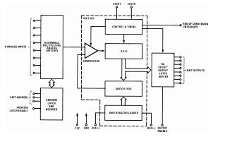
ADC0808 Block Diagram
The ADC0808 IC is a typical ADC module for projects that require an external ADC. It's a 28-pin 8-bit ADC module with eight channels. It can measure up to eight ADC values from 0 to 5V, with a precision of 19.53mV when the voltage reference (Vref –pin 9) is +5V. (Step size). That is, for every 19.53mV rise on the input side, the output side will increase by one bit.
This IC is ideal for usage with microprocessors such as the Raspberry Pi, Beaglebone, and other similar devices. Alternatively, it can be used as a stand-alone ADC module. Every ADC module needs a clock to work, and this IC needs an external clock pulse to function.
Because the ADC0808 IC can measure up to eight analogue voltages and lacks an inbuilt clock, it requires somewhat more components to function than its predecessor, the ADC0804. +5V can be used to power the IC. To obtain the output, the Vref + and the Output enable should both be powered up to +5V. When the V ref + is powered with +5V, the IC will operate with a step size of 19.53mV. The external clock, which can be an oscillator circuit or a pulse generated by an MCU/MPU, should be linked to the clock pin.
Pins IN1 to IN7 can receive the correct analogue voltage, however, the IC can only read the voltage of one channel at a time. The pins ADD A, ADD B and ADD C can be used to select the channel. To access the relevant analogue channel, these three bits must be set as given in the table below. Once the channel has been established, it should be activated by briefly driving the Address latch enabled (ALE) pin high.
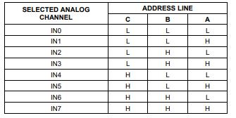
ADC0808-Analog Channel Selection
The analogue voltage should be connected to the V in(+) pin, and the digital output will be produced from pins 2-1 (OUT 1) to 2-8 (OUT 8) as illustrated in the diagram. For the ADC conversion to work, another end of the voltage source (sensor/module) must also be grounded to the circuit. Now, in order for the ADC conversion to begin, we must set the START pin to high as soon as the EOC pin is set to high. This can be accomplished either through programming or by connecting the EOC pin to the START pin as seen in the circuit below.
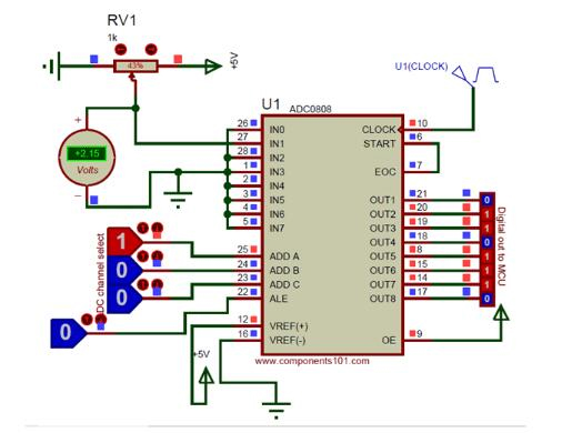
How to use ADC0808

Texas Instruments (TI) emerges as a globally recognized semiconductor manufacturer expanded into 35 countries. It has seen rapid growth. In 1958, TIer firstly introduced the working integrated circuit. And today more than 30,000 TIers worldwide are committed to designing, manufacturing, and selling analogue and embedded processing chips. They aspire to solve challenges as well as change the world through their technologies.
Download datasheets and manufacturer documentation for Texas Instruments ADC0808CCN.
Download datasheets and manufacturer documentation for ADC0808CCN
TAGS
Comments