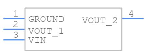
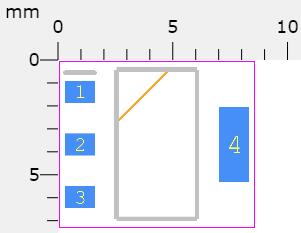
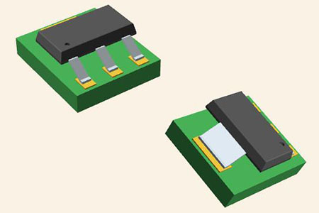
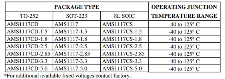
The AMS1117 is relatively simple to operate. If the voltage regulator is a fixed voltage regulator, simply supply power to the IC through the VIN pin, and the regulated output can be found on the Vout pin. In this situation, the Adj/Ground pin is only used as a ground pin and is grounded. A capacitor can also be added to the output side of the circuit to filter out noise. Below is a circuit diagram for a variable output regulator.
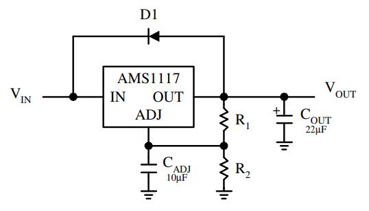
AMS1117 Circuit
To determine the output voltage of an adjustable type voltage regulator, two external resistors are required. The output voltage of the regulator is determined by the resistors R1 and R2. A reference circuit schematic with adjustable voltage is presented below. The CAdj capacitor is an optional component that can be used to increase ripple rejection. The input and output noise is filtered by the other two capacitors.
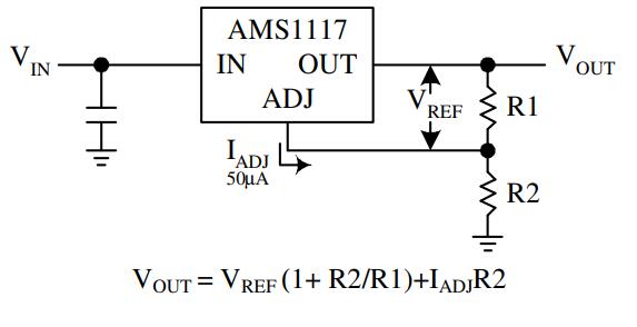
AMS1117 Circuit
Below are the formulas for calculating the output voltage of the AMS1117 regulator. R1 and R2 should be set to the output voltage required for your project. It's important to remember that R1 should be smaller than 1k. If you wish to change the voltage in real-time, use a variable resistor at R2.
VOUT = VREF (1 + R2/R1) + IADJR2
The AMS1117, which can be used as a fixed voltage or variable voltage regulator, is frequently used in battery charging circuits and can also be programmed to give negative voltage if necessary. More application circuits for this IC can be found in the datasheet at the bottom of this page.