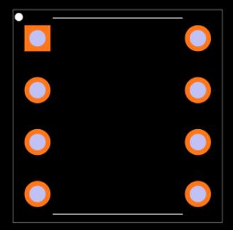
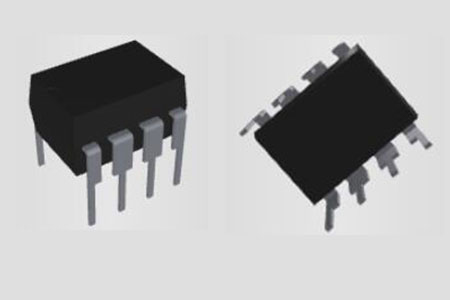
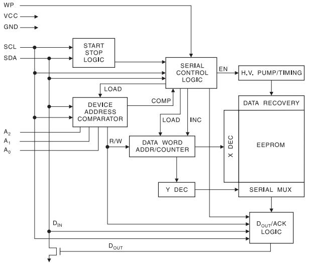
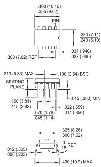
It has a simple interface that allows you to connect it to a microcontroller with only 5 pins. The AT24C32 IC's interface schematic is shown below.

Pin 6 of the AT24C32 IC is connected to the microcontroller's Serial clock pin, while Serial Data pin 5 is connected to the microcontroller's Serial Data pin (SDA). Two pull-up resistors are used to pull the SCK and SDA pins high (4.7k). During the off-season, this will maintain the bus running at a high level.
Select pins A0, A1, and A2 are only useful if multiple EEPROMs are attached to the same microcontroller; otherwise, these pins can be directly grounded. We've linked the three pins to the PIO pins in the circuit diagram above so that we can utilize more than one EEPROM IC if necessary.
In the AT24C32 IC, Pin 7 is used to improve data security. Only when the WP pin is held low can data be written or deleted (logic 0). The data written to the EEPROM, on the other hand, will remain unmodified.