TOP 4 ELECTRONICS PROJECTS USING BT136 TRIAC
The BT136 is TRIAC with a 4A maximum terminal current. This passage is going to tell you everything about BT136.

The BT136 is TRIAC with a 4A maximum terminal current. This passage is going to tell you everything about BT136.
1053
Mar 31, 2022
Elroy Forster
TOP 4 ELECTRONICS PROJECTS USING BT136 TRIAC
The BT136 is TRIAC with a 4A maximum terminal current. This passage is going to tell you everything about BT136.
BT136
BT136 is a type of electronic component, which is a triac.
The thyristor is also the abbreviation of the thyristor rectifier element. It is a high-power semiconductor device with a four-layer structure with three PN junctions, which is generally formed by reversely connecting two thyristors. Its function is not only to rectify, but also to be used as a non-contact switch to quickly turn on or off the circuit, realize the inversion of the direct current into the alternating current, the alternating current of one frequency into the alternating current of another frequency, and so on.
The thyristor, like other semiconductor devices, has the advantages of small size, high efficiency, good stability, and reliable operation. With its emergence, semiconductor technology has moved from the weak current field to the strong current field and has become a component used in industries, agriculture, transportation, military scientific research, as well as commercial and civilian electrical appliances.
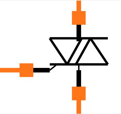
Symbol
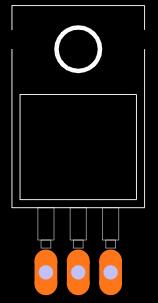
Footprint
Changjiang Electronics Tech (CJ) BT136 technical specifications, attributes, parameters and parts with similar specifications to Changjiang Electronics Tech (CJ) BT136.
Changjiang Electronics Tech (CJ) BT136 technical specifications, attributes, parameters and parts with similar specifications to Changjiang Electronics Tech (CJ) BT136.
| Product Attribute | Attribute Value | |
|---|---|---|
| Package / Case | TO-220(TO-220-3) | |
| Packaging | Tube-packed | |
| Type | Two-way thyristor |
| Product Attribute | Attribute Value | |
|---|---|---|
| Voltage - Gate Trigger (Vgt) (Max) | 1.45V | |
| Current - Gate Trigger (Igt) (Max) | 10mA | |
| Current - On State (It (RMS)) (Max) | 6A |
| Product Attribute | Attribute Value | |
|---|---|---|
| Voltage - Off State (Max) | 600V | |
| RoHS Status | RoHS Compliant |
1. Direct triggering from low power drivers and logic ICS
2. High blocking voltage capability
3. Low holding current for low current loads and lowest EMI at commutation
4. Planar passivated for voltage ruggedness and reliability
5. Triggering in all four quadrants
6. Very sensitive gate
7. 2A Peak gate current
8. 0.5W Average gate power
The applications of TRIAC include the following.
1. Because of the bidirectional control of alternating current, these components are used as different controllers for AC, fan, heater, static switch with three positions, triggering devices for silicon controlled rectifiers, light dimmers, etc.
2. Triac is used as a switch
3. It is used as a High power switch
4. Used to control phase
5. Strode lights
6. Speed control of AC motor
7. Used in circuits of noise coupling
8. AC loads controlling with MPU or MCU
9. Power control of AC or DC
Since TRIACS deal with AC voltages, the circuit involving them has to be designed properly to avoid problem some tips are shared below
1. All TRIAC circuits suffer from an effect called Rate Effect. This occurs when the TRIAC is switching frequently and a sudden high voltage occurs at either main terminal of the TRIAC and damages the TRIAC itself. It can be avoided by using a snubber circuit.
2. Similarly there is another effect called the backlash effect. This occurs due to the capacitance that gets accumulated between the two terminals of the MT1 and MT2 of the TRIAC. Due to this, the TRIAC will not turn on even if the gate voltage is applied. This problem can be solved by providing resistance in series for the capacitance to discharge.
3. When controlling the output AC voltage for dimmer or speed control applications a Zero crossing method is always recommended to be used.
4. In switching circuits the TRIAC is easily subjected to harmonics and EMI interference hence should be isolated from other digital electronics.
5. There is a chance of backward current when the TRIAC is switching inductive loads, so an alternate discharge path has to be provided for the load to drain the inrush current.

| Pin Number | Pin Name | Description |
| 1 | Main Terminal 1 | Connected to Phase or neutral of AC mains |
| 2 | Main Terminal 2 | Connected to Phase or neutral of AC mains |
| 3 | Gate | Used to trigger the SCR. |
With a maximum terminal current of 4A, the BT136 is a TRIAC. The BT136's gate threshold voltage is likewise very low, allowing it to be driven by digital circuits.
TRIACs are often utilized for switching AC applications since they are bi-directional switching devices. So, if you want to use a digital device like a microcontroller or a microprocessor to manage (dim, speed control) an AC load that consumes less than 6A, the BT136 can be a perfect choice.
Four quadrants sensitive gate triac with planar passivation in a SOT78 plastic package for general purpose bidirectional switching and phase control applications. This "series E" sensitive gate triac is designed to connect directly to microcontrollers, logic integrated circuits, and other low-power gate trigger circuits.
The disadvantages of TRIAC include the following.
1. More care needs to be taken while choosing a gate triggers circuit because a TRIAC device activates in both the biased conditions.
2. These are less reliable as compared to thyristors.
3. As compared to thyristors, these have less dv/dt rating
4. The switching frequencies of TRIACs are extremely small.
A TRIAC can be used in a variety of ways, and because the device is bi-directional, the TRIAC gate can be triggered by either positive or negative voltage. As a result, the TIRAC can be used in four different modes. If you want to learn more about switching modes, check this article. Below is a simple TRIAC switching circuit.
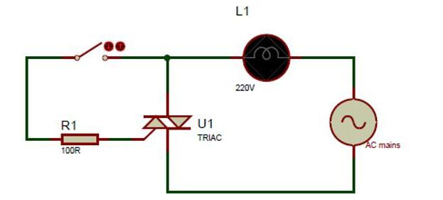
The TRIAC in this circuit is controlled by the switch; when the switch is pressed, the TRIAC closes the connection between the ACbulb and the AC mains. For this to happen, the TRIAC's gate pin must be exposed to a voltage larger than the threshold gate voltage, as well as a current greater than the gate trigger current. This will activate the TRIAC.
Because the TRIAC and SCR have many of the same features, the TRIAC will not turn off when the gate voltage is removed, just like the SCR. To switch off the SCR again, we need a particular form of circuit called a commutation circuit.
Package Name: TO-220AB
Package Description: plastic single-ended package; heatsink mounted; 1 mounting hole; 3-lead TO-220AB
Package Version: SOT78
Package Outline:

TAGS
Comments