COMPARATOR, DUAL, MICROPWR, 8SOIC
LM393D is a low-power, dual-voltage comparator. This blog mainly introduces pinout, specifications, applications, and other detailed information about STMicroelectronics LM393D.

COMPARATOR, DUAL, MICROPWR, 8SOIC LM393D is a low-power, dual-voltage comparator. This blog mainly introduces pinout, specifications,
208
Mar 4, 2021
Camille
COMPARATOR, DUAL, MICROPWR, 8SOIC
LM393D is a low-power, dual-voltage comparator. This blog mainly introduces pinout, specifications, applications, and other detailed information about STMicroelectronics LM393D.
LM393D
| Quantity | Unit Price | Ext. Price |
|---|---|---|
| 1+ | $1.43403 | $1.43 |
| 10+ | $1.35286 | $13.53 |
| 100+ | $1.27628 | $127.63 |
| 500+ | $1.20404 | $602.02 |
| 1000+ | $1.13589 | $1135.89 |
The LM393 devices consist of two independent low voltage comparators designed specifically to operate from a single supply over a wide range of voltages. Operation from split power supplies is also possible. These comparators also have a unique characteristic in that the input common-mode voltage range includes ground even though operated from a single power supply voltage.
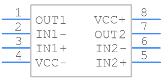
PCB Symbol - STMicroelectronics LM393D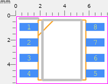 PCB Footprint- STMicroelectronics LM393D
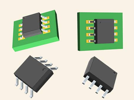 3D Model - STMicroelectronics LM393D
Wide single-supply voltage range or dual supplies: 2 V to 36 V or ±1 V to ±18 V
Very low supply current (0.45 mA) independent of supply voltage (1 mW/comparator at 5 V)
Low input bias current: 20 nA typ.
Low input offset current: ±3 nA typ.
Low input offset voltage: ±1 mV typ.
Input common-mode voltage range includesground
Low output saturation voltage: 80 mV typ. (Isink = 4 mA)
Differential input voltage range equal to the supply voltage
TTL, DTL, ECL, MOS, CMOS compatible outputs
STMicroelectronics LM393D technical specifications, attributes, parameters and parts with similar specifications to STMicroelectronics LM393D.
STMicroelectronics LM393D technical specifications, attributes, parameters and parts with similar specifications to STMicroelectronics LM393D.
| Product Attribute | Attribute Value | |
|---|---|---|
| Lifecycle Status | ACTIVE (Last Updated: 7 months ago) | |
| Factory Lead Time | 25 Weeks | |
| Mount | Surface Mount | |
| Mounting Type | Surface Mount | |
| Package / Case | 8-SOIC (0.154, 3.90mm Width) | |
| Number of Pins | 8Pins | |
| Weight | 4.535924g | |
| Current - Supply (Nom) | 1mA | |
| Operating Temperature | 0°C~70°C | |
| Packaging | Tube | |
| JESD-609 Code | e4 | |
| Part Status | Active | |
| Moisture Sensitivity Level (MSL) | 1 (Unlimited) | |
| Number of Terminations | 8Terminations | |
| ECCN Code | EAR99 | |
| Type | General Purpose | |
| Terminal Finish | Nickel/Palladium/Gold (Ni/Pd/Au) | |
| Max Power Dissipation | 710mW | |
| Terminal Position | DUAL | |
| Terminal Form | GULL WING |
| Product Attribute | Attribute Value | |
|---|---|---|
| Peak Reflow Temperature (Cel) | 260 | |
| Number of Functions | 2Functions | |
| Supply Voltage | 5V | |
| Time@Peak Reflow Temperature-Max (s) | 30 | |
| Base Part Number | LM393 | |
| Pin Count | 8 | |
| Current - Supply (Max) | 1mA | |
| Output Type | CMOS, DTL, ECL, MOS, Open-Collector, TTL | |
| Power Supplies | 5V | |
| Number of Circuits | 2Circuits | |
| Power Dissipation | 710mW | |
| Current - Output | 18mA | |
| Propagation Delay | 1.3 μs | |
| Quiescent Current | 2.5mA | |
| Turn On Delay Time | 1.3 μs | |
| Response Time | 1.3 μs | |
| Voltage - Supply, Single/Dual (±) | 2V~36V ±1V~18V | |
| Output Current per Channel | 18mA | |
| Input Offset Voltage (Vos) | 1mV | |
| Voltage Gain | 106.02dB |
| Product Attribute | Attribute Value | |
|---|---|---|
| Average Bias Current-Max (IIB) | 0.4μA | |
| Supply Voltage Limit-Max | 36V | |
| Max Input Current | 250nA | |
| Dual Supply Voltage | 9V | |
| Input Bias Current | 250nA | |
| Max Junction Temperature (Tj) | 150°C | |
| Voltage - Input Offset (Max) | 5mV @ 30V | |
| Current - Input Bias (Max) | 0.25μA @ 5V | |
| Ambient Temperature Range High | 70°C | |
| Natural Thermal Resistance | 125 °C/W | |
| Current - Output (Typ) | 18mA @ 5V | |
| Height | 1.75mm | |
| Length | 4.9mm | |
| Width | 3.9mm | |
| REACH SVHC | No SVHC | |
| Radiation Hardening | No | |
| RoHS Status | ROHS3 Compliant | |
| Lead Free | Lead Free |
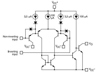 LM393D Schematic diagram
|
Part Number |
Description |
Manufacturer |
|
LM393DG4 AMPLIFIER CIRCUITS |
Dual differential comparator, commercial grade 8-SOIC 0 to 70 |
Texas Instruments |
|
LM393N/NOPB AMPLIFIER CIRCUITS |
Low Power Low Offset Voltage Dual Comparator 8-PDIP 0 to 70 |
Texas Instruments |
|
LM393M/NOPB AMPLIFIER CIRCUITS |
IC DUAL COMPARATOR, 9000 uV OFFSET-MAX, 1300 ns RESPONSE TIME, PDSO8, LEAD FREE, SOIC-8, Comparator |
National Semiconductor Corporation |
|
LM393MX/NOPB AMPLIFIER CIRCUITS |
Low Power Low Offset Voltage Dual Comparator 8-SOIC 0 to 70 |
Texas Instruments |
|
LM393YDT AMPLIFIER CIRCUITS |
DUAL COMPARATOR, 9000uV OFFSET-MAX, 1300ns RESPONSE TIME, PDSO8, LEAD FREE, MICRO, PLASTIC, SOP-8 |
STMicroelectronics |
|
LM393D AMPLIFIER CIRCUITS |
Dual differential comparator, commercial grade 8-SOIC 0 to 70 |
Texas Instruments |
|
LM393M AMPLIFIER CIRCUITS |
Comparator |
Bay Linear Inc |
|
LM393MX_NL AMPLIFIER CIRCUITS |
Comparator, 2 Func, 9000uV Offset-Max, 1400ns Response Time, BIPolar, PDSO8, SOP-8 |
Fairchild Semiconductor Corporation |
|
LM393DRG3 AMPLIFIER CIRCUITS |
Dual differential comparator, commercial grade 8-SOIC 0 to 70 |
Texas Instruments |
|
LM393DG AMPLIFIER CIRCUITS |
Comparator, Dual, Low Offset Voltage, SOIC-8 Narrow Body, 98-TUBE |
ON Semiconductor |
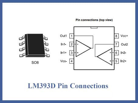
The LM393 applications are very similar to the LM311 Comparator IC, with a few minor differences in requirements. Aside from that, the LM311 can be considered a near substitute for the LM393. The LM393 has both an inverting and non-inverting pin, as do all voltage comparators. The output (pin 7) will be high if the voltage at the Non-Inverting Terminal (pin 2) is higher than the voltage at the Inverting Terminal (pin 2), otherwise, the output will be low.
Since this is the most common configuration for digital circuits, we'll assume the LM393 is operated by a +5V supply voltage circuit. The VCC+ (pin 8) is connected to the +5V supply voltage in this form, while the VCC (pin 4) is grounded to maintain a 0V potential. The Inverting Terminal is set to 2.5V in the circuit below, and the Non-Inverting Terminal voltage is varied with a potentiometer. When pin 2 has a higher voltage than pin 7, the output voltage remains high, and vice versa
If you want to manually change the DC-Offset voltage, use pins 5 and 6 on the Op-amp to set the balance voltage. Normally, these pins are not used because the Input Offset can be managed much better. Pins 5 and 6 should be shorted when not in use, as seen above. You'll also note that the transistor's collector pin (pin 7) is used for output while the emitter pin (pin 1) is grounded; this is known as a "Collector output Circuit," although this isn't always the case.
Voltage Comparator circuits
Can drive Relay, Lamp, Motor Etc
Zero Crossing detector
Peak voltage Detector
High Voltage protection/Warning
Oscillator circuits
STMicroelectronics is a global independent semiconductor company and is a leader in developing and delivering semiconductor solutions across the spectrum of microelectronics applications. An unrivaled combination of silicon and system expertise, manufacturing strength, Intellectual Property (IP) portfolio, and strategic partners positions the Company at the forefront of System-on-Chip (SoC) technology, and its products play a key role in enabling today's convergence trends.
Download datasheets and manufacturer documentation for STMicroelectronics LM393D.
Download datasheets and manufacturer documentation for LM393D
TAGS
Comments