A typical application circuit for the DS1307 from the DS1307 datasheet is shown below.
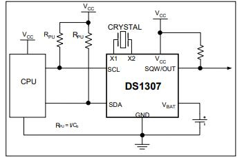
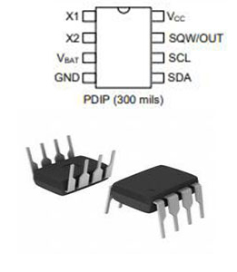
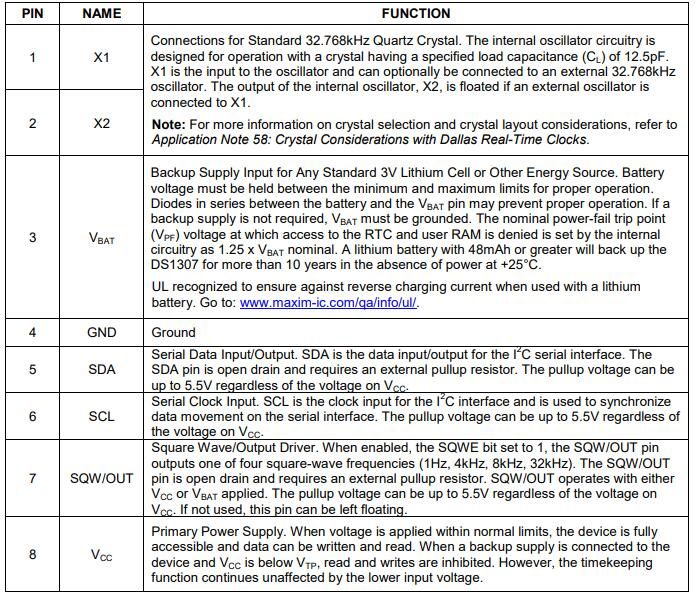
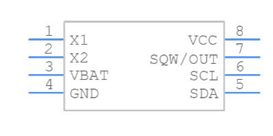
As you can see the IC has SCL (Serial Clock) and SDA (Serial Data) pins using which it communicates to the CPU, both these pins have to be pulled high using a resistor. The IC can be powered by providing 5V on the Vcc pin, when the power fails it will automatically switch to the battery-operated mode in which it will obtain power with Lithium cell connected to pin Vbat and ground.
The pins X1 and X2 are used to connect the crystal oscillator; typically a 32.7KHz Quartz crystal is used. The SQW pin is used to provide a PWM square wave of programmable frequencies in the range of 1Hz, 4KHz, 8KHZ or 32KHz. This pin also requires a pull-up resistor. Data between the CPU and RTC IC is exchanged only through the I2C protocol. Both Read and write happens through this communication. The IC can provide details like Real-Time Clock Counts Seconds, Minutes, Hours, Date of the Month, Month, Day of the Week, and Year with Leap-Year Compensation Valid Up to 2100.