ATTENTION: Due to increased demand and order volume, processing time may take an additional 1-3 business days.
HomeCommunitySubjectDS17285E-3+ Real Time Clock: Pinout, Equivalent and Datasheet

DS17285E-3+ Real Time Clock: Pinout, Equivalent and Datasheet

IC RTC CLK/CALENDAR PAR 28-TSOP The DS17285E-3+ is a successor to the DS1285 real-time clock (RTC). The device provides 18 bytes of real-time clock/calendar, alarm, and control/status registers and 114 bytes of nonvolatile battery-backed RAM.

170

Apr 20, 2022

Rae Paul

What is RTC(REAL TIME CLOCK) ? | RTC Working | RTC Uses | RTC Diagram | (CMOS)Clock In Computer


IC RTC CLK/CALENDAR PAR 28-TSOP

The DS17285E-3 is a successor to the DS1285 real-time clock (RTC). The device provides 18 bytes of real-time clock/calendar, alarm, and control/status registers and 114 bytes of nonvolatile battery-backed RAM. The device also provides additional extended RAM in either 2kbytes. The device is accessed by a multiplexed address/data bus. Furthermore, Huge range of Semiconductors, Capacitors, Resistors and IcS in stock. Welcome RFQ.
 

Inquiry
Min.: 1 Mult.: 1
Price not displayed? Not available to buy online? Please send an RFQ, and we will respond immediately.
Quick Links

DS17285E-3+ Pinout

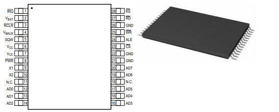
The following figure is the diagram of DS17285E-3+ Pinout.

Pinout

DS17285E-3+ CAD Model

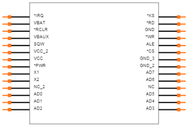
The followings are DS17285E-3+ Symbol and Footprint.

Symbol


Footprint

DS17285E-3+ Description

The DS17285E-3+ Real Time Clock is designed to be successors to the industry-standard DS12885 and DS12887. The DS17285E-3+ (hereafter referred to as the DS17x85) provides a real-time clock/calendar, one time-of-day alarm, three maskable interrupts with a common interrupt output, a programmable square wave, and 114 bytes of battery-backed NV SRAM. The DS17x85 also incorporates a number of enhanced functions including a silicon serial number, power-on/off control circuitry, and 2k, 4k, or 8kbytes of battery-backed NV SRAM. The DS17x85 power-control circuitry allows the system to be powered on by an external stimulus such as a keyboard or by a time-and-date (wake-up) alarm. The PWR output pin is triggered by one or either of these events, and is used to turn on an external power supply. The PWR pin is under software control, so that when a task is complete, the system power can then be shut down.

For all devices, the date at the end of the month is automatically adjusted for months with fewer than 31 days, including correction for leap years. It also operates in either 24-hour or 12-hour format with an AM/PM indicator. A precision temperature-compensated circuit monitors the status of VCC. If a primary power failure is detected, the device automatically switches to a backup supply. A lithium coin cell battery can be connected to the VBAT input pin on the DS17285E-3+ to maintain time and date operation when primary power is absent. The DS17285E-3+ includes a VBAUX input used to power auxiliary functions such as PWR control. The device is accessed through a multiplexed byte-wide interface.

This article will introduce DS17285E-3+ systematically from its features, pinout to its specifications, applications, also including DS17285E-3+ datasheet and so much more.

DS17285E-3+ Features

● RTC Counts Seconds, Minutes, Hours, Day, Date, Month, and Year with Leap Year Compensation Through 2099

● Optional +3.0V or +5.0V Operation

● SMI Recovery Stack

● 64-Bit Silicon Serial Number

● Power-Control Circuitry Supports System Power-On from Date/Time Alarm or Key Closure

● Crystal Select Bit Allows Operation with 6pF or 12.5pF Crystal

● 12-Hour or 24-Hour Clock with AM and PM in 12-Hour Mode

● 114 Bytes of General-Purpose, Battery-Backed NV SRAM

● Extended Battery-Backed NV SRAM: 2048 Bytes

● RAM Clear Function

● Interrupt Output with Six Independently Maskable Interrupt Flags

● Time-of-Day Alarm Once per Second to Once per Day

● End of Clock Update Cycle Flag

● Programmable Square-Wave Output

● Automatic Power-Fail Detect and Switch Circuitry

● Available in PDIP, SO, or TSOP Package

● Optional Industrial Temperature Range Available

● Underwriters Laboratory (UL) Recognized

Specifications

Maxim Integrated DS17285E-3+ technical specifications, attributes, parameters and parts with similar specifications to Maxim Integrated DS17285E-3+.

undefined Tech Specifications

undefined undefined technical specifications, attributes, parameters and parts with similar specifications to undefined undefined.

Product Attribute Attribute Value
0 Products View Similar

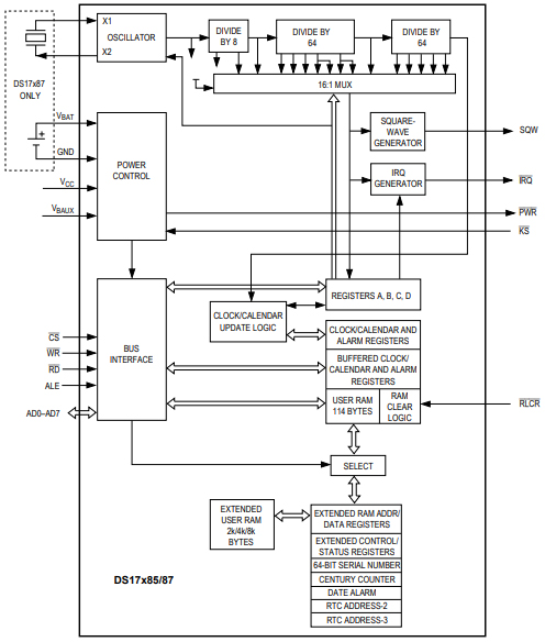
DS17285E-3+ Functional Block Diagram

The following is the Functional Diagram of DS17285E-3+.

Functional Diagram

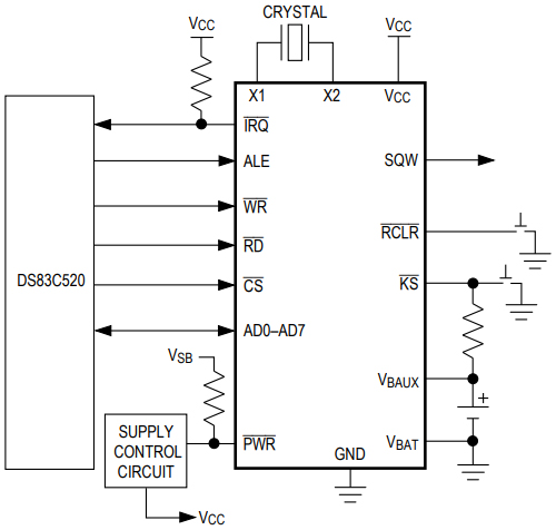
DS17285E-3+ Typical Operating Circuit

The following diagram shows the DS17285E-3+ Typical Operating Circuit.

Typical Operating Circuit

DS17285E-3+ Equivalent

    Model number                 Manufacturer                                                 Description
DS17285EN-5 Dallas Semiconductor Real Time Clock, Volatile, 1 Timer(s), CMOS, PDSO28, TSOP-28
DS17285E-3 Dallas Semiconductor Real Time Clock, Volatile, 1 Timer(s), CMOS, PDSO28, TSOP-28
DS17285E-5 Rochester Electronics LLC 1 TIMER(S), REAL TIME CLOCK, PDSO28, TSOP-28
DS17285EN-3 Maxim Integrated Products Real Time Clock, Volatile, 1 Timer(s), CMOS, PDSO28, TSOP-28

DS17285E-3+ Applications

● Embedded Systems

● Utility Meters

● Security Systems

● Network Hubs, Bridges, and Routers


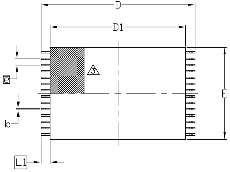
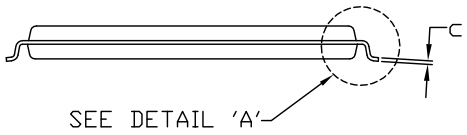
DS17285E-3+ Package

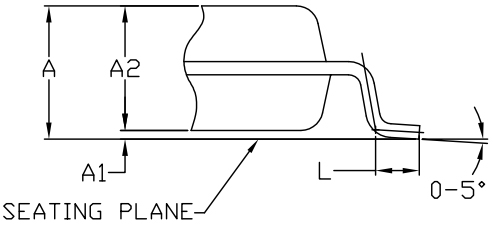
The following diagrams show the DS17285E-3+ Package.

Top View


Side View


Detail A


DS17285E-3+ Manufacturer

The market is evolving. The rules are changing. To keep your time to market short, you need integration at every level—from silicon to the supply chain. Count on Maxim Integrated to help you overcome design and architectural challenges, with integrated solutions for the industrial, medical, consumer, automotive, energy, computing, and communications realms. Maxim Integrated is also your source for power, interface, and even digital products that work in the analog world. And they're glad to support you with reference designs, tools, technical documents, packaging, and more. We invite you to explore their latest analog integration offerings.

Datasheet PDF

undefined Documents

Download datasheets and manufacturer documentation for

Frequently Asked Questions

How many pins of DS17285E-3+?
28 Pins.
What’s the operating temperature of DS17285E-3+?
0°C~70°C.
What’s the supply voltage of DS17285E-3+?
2.7V~3.7V.
What is the essential property of the DS17285E-3+?
The DS17285E-3+ is a successor to the DS1285 real-time clock (RTC). The device provides 18 bytes of real-time clock/calendar, alarm, and control/status registers and 114 bytes of nonvolatile battery-backed RAM.
FAQ
How many pins of DS17285E-3+?
28 Pins.
What’s the operating temperature of DS17285E-3+?
0°C~70°C.
What’s the supply voltage of DS17285E-3+?
2.7V~3.7V.
What is the essential property of the DS17285E-3+?
The DS17285E-3+ is a successor to the DS1285 real-time clock (RTC). The device provides 18 bytes of real-time clock/calendar, alarm, and control/status registers and 114 bytes of nonvolatile battery-backed RAM.

TAGS

Share