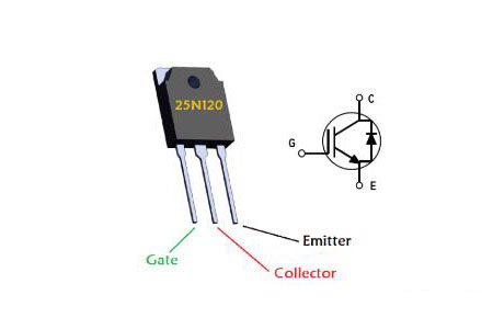
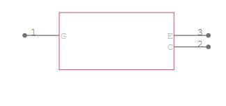
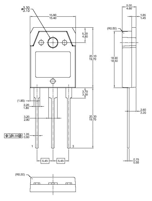
The pin-out of an IGBT shows that it is a hybrid of MOSFET and BJT. On the input side, it's comparable to a MOSFET, and on the output side, it's similar to a BJT, with Collector and Emitter. This means that an IGBT is simply a MOSFET with a BJT on the output side to take advantage of the advantages of both a MOSFET and a BJT.
In the same way that the gate pin of a MOSFET must be triggered with the minimum gate voltage to close the switch, the gate pin of an IGBT must be triggered with the minimum gate voltage to close the switch. The needed gate trigger voltage can be estimated using the collector-emitter voltage and collector current that must be switched, using the graph in the datasheet shown below.
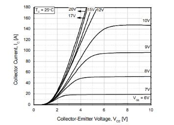
How to use FGA25N120
Like a MOSFET, once the gate is triggered, the IGBT will stay on even if the trigger voltage is withdrawn. This is because the input gate pin of an IGBT has a gate capacitance. To switch off the device, just connect the gate pin of the IGBT to the ground to discharge the gate capacitance. As a result, the Gate pin of an IGBT is usually linked to the ground through a 10k pull-down resistor or a gate driver IC such as the IR2104.
When using IGBTs in switching circuits, it's important to avoid using them in high-frequency designs since the IGBT's collector-emitter voltage drop (switching loss) increases as the switching frequency rises. In the datasheet, you'll find a graph for the same.