PIC16F877A a basic Introduction
8-bit Microcontrollers - MCU 14KB 368 RAM 33 I/O
PIC16F877A is a 40-pin enhanced flash microcontroller. You'll learn how to interface a stepper motor with a PIC16F877A microcontroller in this post.

8-bit Microcontrollers - MCU 14KB 368 RAM 33 I/O PIC16F877A is a 40-pin enhanced flash microcontroller. You'll learn how to interface a stepper motor with a PIC16F877A microcontroller in this post.
192
Mar 29, 2022
Andy Cocker
PIC16F877A a basic Introduction
8-bit Microcontrollers - MCU 14KB 368 RAM 33 I/O
PIC16F877A is a 40-pin enhanced flash microcontroller. You'll learn how to interface a stepper motor with a PIC16F877A microcontroller in this post.
PIC16F877A-I/P

PIC16F877A Pinout
Symbol

PIC16F877A Symbol
Footprint
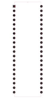
PIC16F877A Footprint
3D Model
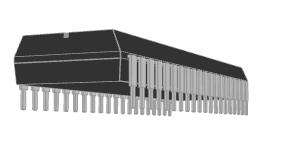
PIC16F877A 3D Model
The following diagram of PIC16F777A is given below

PIC16F877A Block Diagram
Microchip Technology PIC16F877A-I/P technical specifications, attributes, parameters and parts with similar specifications to Microchip Technology PIC16F877A-I/P.
Microchip Technology PIC16F877A-I/P technical specifications, attributes, parameters and parts with similar specifications to Microchip Technology PIC16F877A-I/P.
| Product Attribute | Attribute Value | |
|---|---|---|
| Factory Lead Time | 7 Weeks | |
| Mount | Through Hole | |
| Mounting Type | Through Hole | |
| Package / Case | 40-DIP (0.600, 15.24mm) | |
| Number of Pins | 40Pins | |
| Data Converters | A/D 8x10b | |
| Current - Supply (Nom) | 1.6mA | |
| Number of I/Os | 33I/Os | |
| Watchdog Timers | Yes | |
| Operating Temperature | -40°C~85°C TA | |
| Packaging | Tube | |
| Series | PIC® 16F | |
| Published | 1997 | |
| JESD-609 Code | e3 | |
| Pbfree Code | yes | |
| Part Status | Active | |
| Moisture Sensitivity Level (MSL) | 1 (Unlimited) | |
| Number of Terminations | 40Terminations | |
| ECCN Code | EAR99 | |
| Terminal Finish | Matte Tin (Sn) - annealed |
| Product Attribute | Attribute Value | |
|---|---|---|
| Additional Feature | OPERATES AT 4 V MINIMUM SUPPLY | |
| Voltage - Supply | 5V | |
| Terminal Position | DUAL | |
| Frequency | 20MHz | |
| Base Part Number | PIC16F877A | |
| Power Supplies | 5V | |
| Interface | I2C, SPI, SSP, UART, USART | |
| Memory Size | 14kB | |
| Oscillator Type | External | |
| RAM Size | 368 x 8 | |
| uPs/uCs/Peripheral ICs Type | MICROCONTROLLER, RISC | |
| Core Processor | PIC | |
| Peripherals | Brown-out Detect/Reset, POR, PWM, WDT | |
| Program Memory Type | FLASH | |
| Core Size | 8-Bit | |
| Program Memory Size | 14KB 8K x 14 | |
| Connectivity | I2C, SPI, UART/USART | |
| Bit Size | 8 | |
| Access Time | 20 μs | |
| Has ADC | YES |
| Product Attribute | Attribute Value | |
|---|---|---|
| DMA Channels | NO | |
| Data Bus Width | 8b | |
| Number of Timers/Counters | 3Timers/Counters | |
| Address Bus Width | 8b | |
| Density | 112 kb | |
| EEPROM Size | 256 x 8 | |
| CPU Family | PIC | |
| Number of ADC Channels | 8ADC Channels | |
| Voltage - Supply (Max) | 5.5V | |
| Voltage - Supply (Min) | 4.5V | |
| Number of PWM Channels | 2PWM Channels | |
| Number of I2C Channels | 1I2C Channel | |
| Height | 4.06mm | |
| Length | 52.45mm | |
| Width | 14.22mm | |
| REACH SVHC | No SVHC | |
| Radiation Hardening | No | |
| RoHS Status | ROHS3 Compliant | |
| Lead Free | Lead Free |
A stepper motor is a type of motor that uses electrical pulses to generate mechanical movement. A stepper motor, unlike all other motors, moves in steps. The motor's steps are measured in degrees and can vary depending on the application. It takes one step at a time, and each step is the same size as the previous one.
A stepper motor has three excitation modes: wave drive, full drive, and a half drive. Only one winding is activated at a time in wave drive mode, whereas two phases are energized at the same time in full drive mode. In both wave and full drive modes, however, the number of steps is the same. Half drive mode combines wave drive and full drive, i.e. it alternately energizes one and two phases.
The following is a circuit diagram of a stepper motor connecting with a pic16f877a microcontroller:
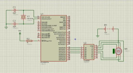
Stepper Motor interfacing with PC16F877A microcontroller
The ULN2003 transistor array chip is the simplest way to connect a stepper motor to a Pic16F877A microcontroller. This IC is used for high current torque motors and has seven Darlington transistor drivers. The four input pins (1B, 2B, 3B, 4B) of the ULN2003 are linked to the lowest significant bits of the microcontroller's PORTD, while the output pins (1C, 2C, 3C, 4C ) are connected to the stepper motor 's 'live' pins, as shown in the circuit diagram.
The stepper motor 's 'common' pins, as well as the ULN2003 's 'COM' pin, are connected to a 12V battery supply.
In the mikroC code editor window, type the following code:
void main()
{
TRISD = 0b0000000; // PORT D as output port
PORTD = 0b1111111;
do
{
PORTD = 0b00000011; // energizing two phases at a time
Delay_ms(500); // delay of 0.5s
PORTD = 0b00000110;
Delay_ms(500);
PORTD = 0b00001100;
Delay_ms(500);
PORTD = 0b00001001;
Delay_ms(500);
}while(1); // loop executed infinite times
}
The code above shows how a stepper motor in full drive mode works. The above code will need to be tweaked somewhat for wave drive and half drive modes. The circuit diagram, on the other hand, remains unchanged. The controller's PORTD has been designated as an output port, which is fed to the ULN2003 driver IC. The input pins of the IC receive the combination of bits from the controller's PORTD, allowing it to turn on and off the motor's various coils.
Stepper motors are widely employed in our everyday lives. Automobiles, digital photocopiers, computer printers, and other home appliances all use them to move the print head carriage. Industrial machines, security, and medical devices all employ stepper motors.
Download datasheets and manufacturer documentation for PIC16F877A-I/P
TAGS
Comments