ATTENTION: Due to increased demand and order volume, processing time may take an additional 1-3 business days.
HomeCommunitySubjectIR2110 Driver IC: Equivalent, Pinout and Test Circuit

IR2110 Driver IC: Equivalent, Pinout and Test Circuit

IC GATE DRVR HALF-BRIDGE 14DIP Hi, fellas.Welcome to the new post today. The IR2110 is a high voltage, high-speed power MOSFET and IGBT driver with independent high and low side referenced output channels.

6797

Sep 4, 2021

Lester Kelsen

2000W SMPS for Audio - HB, PFC with IR2110 Mosfet Driver


IC GATE DRVR HALF-BRIDGE 14DIP

Hi, fellas.Welcome to the new post today. The IR2110 is a high voltage, high-speed power MOSFET and IGBT driver with independent high and low side referenced output channels. This article mainly introduces equivalent, pinout, test circuit, and other detailed information about Infineon Technologies IR2110.
IR2110

8000In Stock
Min.: 1 Mult.: 1
Price not displayed? Not available to buy online? Please send an RFQ, and we will respond immediately.
Quick Links

IR2110 Description

The IR2110 is a high voltage, high-speed power MOSFET and IGBT driver with independent high and low side referenced output channels. It has a floating circuit to handle bootstrap operation. 


The operating supply voltage range for IR2110 is 10 to 20 volt and the output current is 2.5A. IR2210 can withstand voltage up to 500v (offset voltage). Its output pins can provide a peak current of up to 2 amperes. 


It can also be used as an IGBT driver. IR2110 floating circuit can drive high side  MOSFET up to 500 volts. IR2110 comes in a 14 pins through-hole PDIP package and the 16-pin surface mount SOIC package.

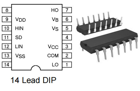
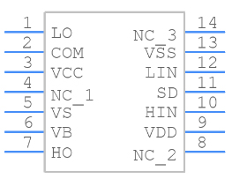
IR2110 Pinout

Pin Number Pin Name Description
1 LO Low side gate drive output
2 COM Low side return
3 VCC Low side supply
5 VS High side floating supply return
6 VB High side floating supply
7 HO High side gate drive output
9 VDD Logic supply
10 HIN Logic input for high side gate driver output (HO), in phase
11 SD Logic input for shutdown
12 LIN Logic input for low side gate driver output (LO), in phase
13 VSS Logic ground

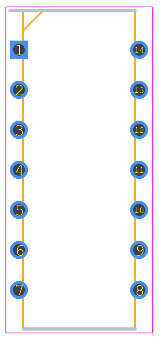
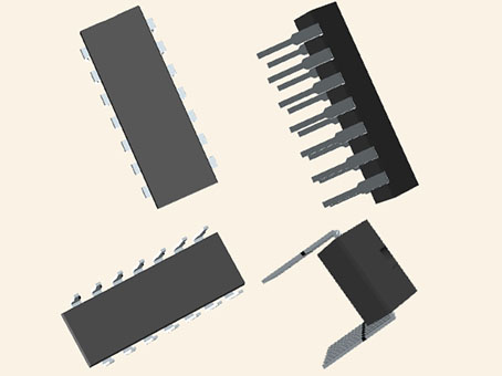
IR2110 CAD Model

Symbol

Footprint

3D Model

IR2110 Features

●Output Current: 2.5A

●Supply Voltage Range: 10V to 20V

●Maximum Turn-On Delay Time: 120 ns

●Maximum Turn-Off Delay Time: 94 ns

●Operating Supply Current: 340 µA

●Rise Time: 35 ns

●Fall Time: 25 ns

●Package: PDIP and SOIC

●Tolerant to negative transient voltage

●DV/DT immune

●Undervoltage lockout for both channels

●Separate logic supply range from 5 to 20V

●Logic and power ground ±5V offset

●CMOS Schmitt-triggered inputs with pull-down

●Cycle by cycle edge-triggered shutdown logic

●Matched propagation delay for both channels

●Outputs in phase with inputs

Specifications

Infineon Technologies IR2110 technical specifications, attributes, parameters and parts with similar specifications to Infineon Technologies IR2110.

IR2110 Tech Specifications

Infineon Technologies IR2110 technical specifications, attributes, parameters and parts with similar specifications to Infineon Technologies IR2110.

Product Attribute Attribute Value
Mounting TypeThrough Hole
Package / Case14-DIP (0.300, 7.62mm)
Surface MountNO
Driver ConfigurationHalf-Bridge
Logic voltage-VIL, VIH6V 9.5V
Operating Temperature-40°C~150°C TJ
PackagingTube
Published1996
Part StatusObsolete
Moisture Sensitivity Level (MSL)1 (Unlimited)
Number of Terminations14Terminations
ECCN CodeEAR99
Product Attribute Attribute Value
Voltage - Supply3.3V~20V
Terminal PositionDUAL
Peak Reflow Temperature (Cel)NOT SPECIFIED
Number of Functions1Function
Supply Voltage15V
Time@Peak Reflow Temperature-Max (s)NOT SPECIFIED
Base Part NumberIR2110
JESD-30 CodeR-PDIP-T14
Qualification StatusNot Qualified
Input TypeNon-Inverting
Rise / Fall Time (Typ)25ns 17ns
Channel TypeIndependent
Product Attribute Attribute Value
Number of Drivers2Drivers
Turn On Time0.15 μs
Output Peak Current Limit-Nom2.5A
Gate TypeIGBT, N-Channel MOSFET
Current - Peak Output (Source, Sink)2A 2A
High Side DriverYES
High Side Voltage - Max (Bootstrap)500V
Length19.305mm
Height Seated (Max)5.33mm
RoHS StatusNon-RoHS Compliant
0 Products View Similar

IR2110 Alternatives

Part Number Description Manufacturer
IR2110PBFDRIVERS AND INTERFACES Half Bridge Based MOSFET Driver, 2.5A, CMOS, PDIP14, LEAD-FREE, PLASTIC, MS-001AC, DIP-14 International Rectifier
IR2110DRIVERS AND INTERFACES Half Bridge Based MOSFET Driver, 2.5A, CMOS, PDIP14, PLASTIC, MS-001AC, DIP-14 Infineon Technologies AG
IR2110L4DRIVERS AND INTERFACES Half Bridge Based MOSFET Driver, 2A, CMOS, MO-036AB, 14 PIN International Rectifier

IR2110 Equivalent

FAN7392, UCC27714, MIC4608

How to use IR2110?

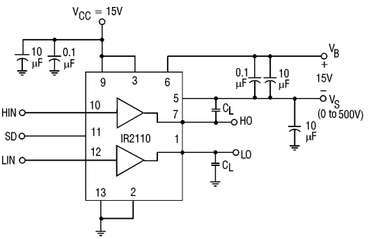
The application circuit for driving MOSFETs in both high and low side configurations using IR2110 is given below. The floating channel is used to drive the N-channel power MOSFET or IGBT in the high side configuration that operates up to 500 volts. HO and LO are Low side gate drive output and High side gate driving output pins.

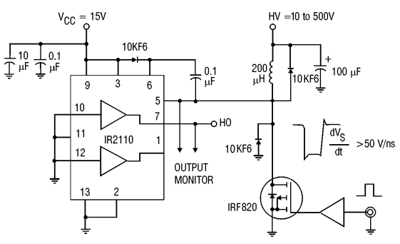
IR2110 Test Circuit

Floating SupplyVoltageTransientTest Circuit

Switching Time Test Circuit

IR2110 Applications

●Used in DC motor driver

●Used in AC Motor Speed control

●Used in Half, full, and three-phase bridge

●Used in Pure sine wave inverter

●Used in Soft starter for three-phase induction motor

●Used in Full and half-bridge motor driver

●Used in Industrial controls

●Used in White goods

IR2110 Manufacturer

Infineon Technologies AG is a German semiconductor manufacturer founded in 1999 when the semiconductor operations of the former parent company Siemens AG were spun off. Infineon has about 46,665 employees and is one of the ten largest semiconductor manufacturers worldwide. It is the market leader in automotive and power semiconductors.

Datasheet PDF

Download datasheets and manufacturer documentation for Infineon Technologies IR2110.

IR2110 Documents

Download datasheets and manufacturer documentation for IR2110

Frequently Asked Questions

1.What role does the chip IR2110 play in the igbt tube drive circuit?
IR2110: It is a high-end and low-end driver, which is equivalent to a stable output in the IGBT drive circuit.
2.What signal does IR2110 pin 10 and 12 input?
It can input PWM wave.
3.Is the output of IR2110's low-end output high level or level?
It can output high-level positive or low-level negative.
FAQ
1.What role does the chip IR2110 play in the igbt tube drive circuit?
IR2110: It is a high-end and low-end driver, which is equivalent to a stable output in the IGBT drive circuit.
2.What signal does IR2110 pin 10 and 12 input?
It can input PWM wave.
3.Is the output of IR2110's low-end output high level or level?
It can output high-level positive or low-level negative.

TAGS

Share