ATTENTION: Due to increased demand and order volume, processing time may take an additional 1-3 business days.
HomeCommunitySubjectIR2113 High And Low Side Driver: 1.2V, 500V IGBT Driver IC, 14 PDIP and Schematic

IR2113 High And Low Side Driver: 1.2V, 500V IGBT Driver IC, 14 PDIP and Schematic

PMIC - Gate Drivers 14-DIP (0.300, 7.62mm) 3.3V~20V -40°C~150°C TJ Non-Inverting IR2113PBF 15V Driver; High and Low Side; 500 V (Max.); 1.2 V (Max.); 0.1 V (Max.); PDIP

178

Nov 20, 2021

Afra Addison

IR2113


PMIC - Gate Drivers 14-DIP (0.300, 7.62mm) 3.3V~20V -40°C~150°C TJ Non-Inverting IR2113PBF 15V Driver; High and Low Side; 500 V (Max.); 1.2 V (Max.); 0.1 V (Max.); PDIP

The IR2113 is a high voltage, high-speed power MOSFET and IGBT driver with independent high and low side referenced output channels. This article will introduce detailed info about IR2113 driver ic.
 

IR2113PBF

14000In Stock
Min.: 1 Mult.: 1
Quantity Unit Price Ext. Price
1+ $3.21626$3.22
10+ $3.03421$30.34
100+ $2.86246$286.25
500+ $2.70043$1350.22
1000+ $2.54758$2547.58
Unit Price:$3.21626
Subtotal: $3.22
Looking for a better price? Want a lower wholesale price? Please send an RFQ, and we will respond immediately.
Quick Links

What is IR2113?

The IR2113 is a high voltage, high-speed power MOSFET and IGBT driver with independent high and low side referenced output channels. The output drivers feature a high pulse current buffer stage designed for minimum driver cross-conduction.

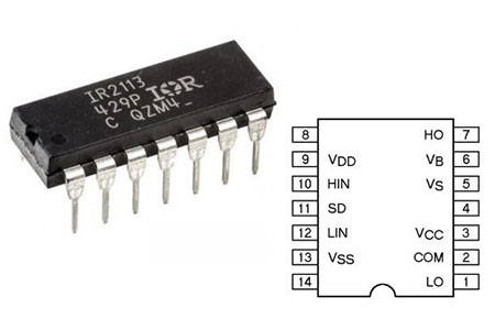
IR2113 Pinout

IR2113 CAD Model

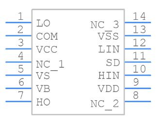
IR2113 Symbol

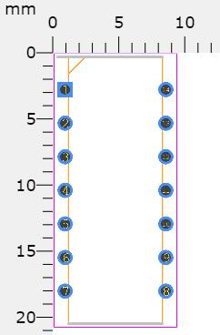
IR2113 Footprint

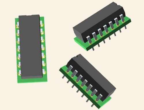
IR2113 3D Model

Specifications

Infineon Technologies IR2113PBF technical specifications, attributes, parameters and parts with similar specifications to Infineon Technologies IR2113PBF.

IR2113PBF Tech Specifications

Infineon Technologies IR2113PBF technical specifications, attributes, parameters and parts with similar specifications to Infineon Technologies IR2113PBF.

Product Attribute Attribute Value
Factory Lead Time12 Weeks
MountSurface Mount, Through Hole
Mounting TypeThrough Hole
Package / Case14-DIP (0.300, 7.62mm)
Number of Pins14Pins
Driver ConfigurationHalf-Bridge
Logic voltage-VIL, VIH6V 9.5V
Turn Off Delay Time20 ns
Operating Temperature-40°C~150°C TJ
PackagingTube
Published1996
Part StatusActive
Moisture Sensitivity Level (MSL)1 (Unlimited)
Number of Terminations14Terminations
TerminationSMD/SMT
ECCN CodeEAR99
TypeIntegrated Circuit (IC)
Max Power Dissipation1.25W
Product Attribute Attribute Value
Voltage - Supply3.3V~20V
Terminal PositionDUAL
Number of Functions1Function
Supply Voltage15V
Base Part NumberIR2113PBF
Number of Outputs2Outputs
Output Voltage20V
Max Output Current2A
Operating Supply Voltage15V
Nominal Supply Current340μA
Power Dissipation1.25W
Output Current2.5A
Max Supply Current340μA
Propagation Delay150 ns
Input TypeNon-Inverting
Turn On Delay Time20 ns
Max Output Voltage20V
Reference Voltage600V
Product Attribute Attribute Value
Rise Time35ns
Fall Time (Typ)25 ns
Min Output Voltage10V
Rise / Fall Time (Typ)25ns 17ns
Channel TypeIndependent
Turn On Time0.15 μs
Output Peak Current Limit-Nom2.5A
Gate TypeIGBT, N-Channel MOSFET
Current - Peak Output (Source, Sink)2A 2A
High Side DriverYES
Height2.35mm
Length10.4902mm
Width7.11mm
REACH SVHCNo SVHC
Radiation HardeningNo
RoHS StatusROHS3 Compliant
Lead FreeContains Lead, Lead Free
0 Products View Similar

IR2113 Features

  • Floating channel designed for bootstrap operation

  • Fully operational to +500V or +600V

  • Tolerant to negative transient voltage dV/dt immune

  • Gate drive supply range from 10 to 20V

  • Under-voltage lockout for both channels

  • 3.3V logic compatible

  • Separate logic supply range from 3.3V to 20V

  • Logic and power ground ±5V offset

  • CMOS Schmitt-triggered inputs with pull-down

  • Cycle by cycle edge-triggered shutdown logic

  • Matched propagation delay for both channels

  • Outputs in phase with inputs

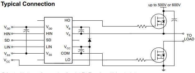
IR2113 Typical Connection

The following is the typical connection of IR2113

IR2113 Typical Connection

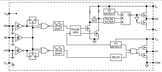
IR2113 Functional Block Diagram

IR2113 Functional Block Diagram

IR2113 Equivalents

IRF470, IR2110, IR1176, IRF450, IRF9460


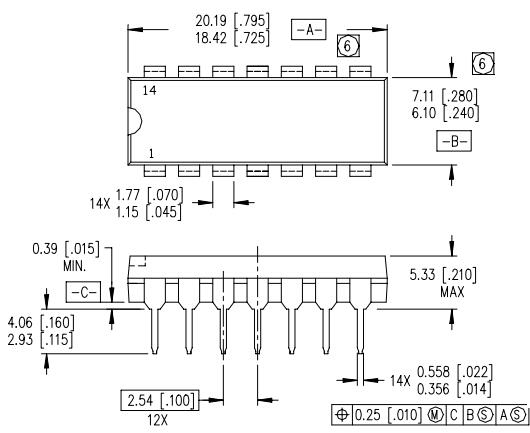
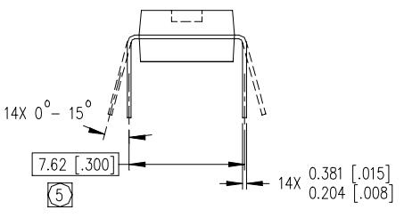
IR2113 Package Outlines

IR2113 Manufacturer

On April 1st, 1999, Siemens Semiconductors became Infineon Technologies. A dynamic more flexible company geared towards success in the competitive, ever-changing world of microelectronics. Infineon is a leading global designer, manufacturer, and supplier of a broad range of semiconductors used in various microelectronic applications. Infineon's product portfolio consists of logic products, including digital, mixed-signal, and analog integrated circuits, as well as discrete semiconductor products.


Datasheet PDF

Download datasheets and manufacturer documentation for Infineon Technologies IR2113PBF.

IR2113PBF Documents

Download datasheets and manufacturer documentation for IR2113PBF

Frequently Asked Questions

What is the use of IR2113?
The IR2113 are high voltage, high-speed power MOSFET and IGBT drivers with independent high and low side referenced output channels. The floating channel can be used to drive an N-channel power MOSFET or IGBT in the high side configuration which operates up to 500 or 600 volts.
How does IR2113 work?
An IR2113 is a power amplifier that accepts a low-power input from a controller IC and produces the appropriate high current gate drive for a power device. To operate a MOSFET/IGBT, typically a voltage has to be applied to the gate that is relative to the source/emitter of the device.
What are the benefits of Gate Drive Control ICs?
The HVAC gate drive solution typically cuts down on component counts and PCB size by 50 percent compared to discrete solutions. These devices offer an improved immunity to voltage spikes and contribute to lower switching losses for the IGBTs and FETs. Fast switching times, under-voltage lockout protection, included dead time are other advantages of these drivers.
FAQ
What is the use of IR2113?
The IR2113 are high voltage, high-speed power MOSFET and IGBT drivers with independent high and low side referenced output channels. The floating channel can be used to drive an N-channel power MOSFET or IGBT in the high side configuration which operates up to 500 or 600 volts.
How does IR2113 work?
An IR2113 is a power amplifier that accepts a low-power input from a controller IC and produces the appropriate high current gate drive for a power device. To operate a MOSFET/IGBT, typically a voltage has to be applied to the gate that is relative to the source/emitter of the device.
What are the benefits of Gate Drive Control ICs?
The HVAC gate drive solution typically cuts down on component counts and PCB size by 50 percent compared to discrete solutions. These devices offer an improved immunity to voltage spikes and contribute to lower switching losses for the IGBTs and FETs. Fast switching times, under-voltage lockout protection, included dead time are other advantages of these drivers.

TAGS

Share