ATTENTION: Due to increased demand and order volume, processing time may take an additional 1-3 business days.
HomeCommunitySubjectIRF1010E N-Channel MOSFET: Datasheet, Pinout, Equivalent

IRF1010E N-Channel MOSFET: Datasheet, Pinout, Equivalent

Transistors - FETs, MOSFETs - Single MOSFET N-CH 60V 84A TO-220AB IRF1010E is an N-Channel Enhancement MOSFET.

1407

Oct 21, 2021

Jocelyn Walter

How to Test MOSFET transistor using Multimeter by some easy methods


Transistors - FETs, MOSFETs - Single MOSFET N-CH 60V 84A TO-220AB

IRF1010E is an N-Channel Enhancement MOSFET. This post will unlock more details about IRF1010E. There is a huge range of Semiconductors, Capacitors, Resistors and ICs in stock. Welcome RFQ.

IRF1010EPBF

20000In Stock
Min.: 1 Mult.: 1
Quantity Unit Price Ext. Price
1+ $1.6289$1.63
10+ $1.5367$15.37
100+ $1.44972$144.97
500+ $1.36766$683.83
1000+ $1.29024$1290.24
Unit Price:$1.6289
Subtotal: $1.63
Looking for a better price? Want a lower wholesale price? Please send an RFQ, and we will respond immediately.
Quick Links

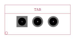
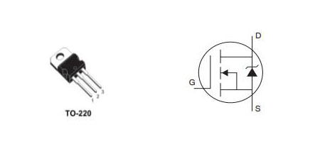
IRF1010E Pinout

IRF1010E Pinout

IRF1010E CAD Model

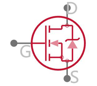
IRF1010E Symbol


3D Model

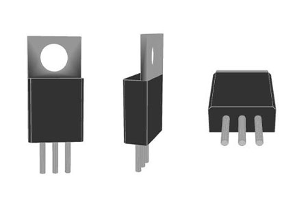
IRF1010E 3D Model

IRF1010E Description

The IRF1010E is an N-Channel Enhancement MOSFET that is optimized for high-speed switching. It also has minimal resistance to turning on. The IRF1010E, like any other MOSFET, is a voltage-controlled device, with the GATE voltage determining the MOSFET state.

Where to use IRF1010E?

There are many reasons for using IRF1010E, here are a few:

  1. When a high-speed SWITCHING device for MEDIUM POWER LOADS is required. Because the IRF1010E is intended specifically for high-speed switching of medium-power loads, it is quite common in such sectors;

  2. When you need a switching device with a low drop. The MOSFET has a very low turn ON resistance, which results in a very low drop during the ON condition, which is required in some applications;

  3. MOSFET power loss is reduced when the drop is low. The system's efficiency will improve with less power loss. As a result, MOSFETs are favoured for applications requiring great efficiency.

How to use IRF1010E?

IRF1010E MOSFET can be used like any other power MOSFETs, so let us consider an application circuit for IRF1010E as shown below.
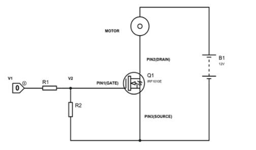
IRF1010E Application Circuit

The IRF1010E is used as a simple switching device in the design above. A tiny motor serves as the LOAD in this circuit. CONTROL UNIT (NOT MICROCONTROLLER) provides the TRIGGER for turning on the MOSFET. MICROCONTROLLER cannot offer voltages higher than +5V. The SOURCE has a solid foundation. The power source is a +12V battery in this case.

CONTROL UNIT trigger voltage = V1

GATE voltage = V2

To provide adequate voltage at GATE, the resistors R1 and R2 form a voltage divider circuit. As a result, they are chosen based on the trigger voltage (V1) of the CONTROL UNIT and the MOSFET GATE threshold voltage.

Consider the CONTROL UNIT, which generates voltage pulses of +12V. A GATE voltage of 10V is also required to totally switch on the MOSFET IRF1010E.

So V1 =+12V and V2 = +10V

We can choose R1 and R2 as,


R1

R2

200Ω

1KΩ

400Ω

2KΩ

2KΩ

10KΩ


Any configuration of the above table will construct a voltage divider circuit that will give accurate +10V at the MOSFET GATE. The current draw from the MOSFET is small, therefore this resistor arrangement can be chosen without it. For most applications, these resistances could be chosen roughly.

Under normal circumstances, the MOSFET in the circuit above will be turned off because there is no GATE voltage. When the MOSFET is turned off, the entire VCC appears across it. The DRAIN current will be 0 in this situation. The MOTOR will sit idle since the DRAIN current is zero.

There will be GATE voltage when the CONTROL UNIT produces voltage pulses. The MOSFET is turned ON when the GATE voltage is present. There will be DRAIN current flowing through the MOTOR as a result of this. The MOTOR stars rotate when the current flows. The MOTOR will continue to rotate until the GATE voltage is reached.

When the CONTROL UNIT output is set to LOW, the GATE voltage is set to LOW as well. When the GATE voltage falls below the threshold voltage, the MOSFET is turned off. The DRAIN current likewise becomes ZERO in the OFF state, putting the MOTOR to a complete stop.

The MOSFET is employed as a switching device in the above scenario, with the control unit providing the trigger. As a result, the IRF1010E can be used as a switching device in any application. The circuit shown above is a rudimentary testing circuit, not a real-world application. HEAT SINK, FLYBACK DIODE, and other essential arrangements must be present in the application circuit.

IRF1010E Feature

 Advanced Process Technology

 Ultra Low On-Resistance 

 Dynamic dv/dt Rating 

 175°C Operating Temperature 

 Fast Switching 

 Fully Avalanche Rated 

 Lead-Free

IRF1010E Application

  • Basically any switching applications

  • speed control units

  • Lighting systems

  • PWM applications

  • Relay drivers

  • Switch-mode power supply

IRF1010E Equivalent

The equivalent for IRF1010E:

  • IRF1407

  • IRFB4110

  • IRFB4110G

  • IRFB4115

  • IRFB4310Z

  • IRFB4310ZG

  • IRFB4410

Specifications

IRF1010EPBF Tech Specifications

Infineon Technologies IRF1010EPBF technical specifications, attributes, parameters and parts with similar specifications to Infineon Technologies IRF1010EPBF.

Product Attribute Attribute Value
Factory Lead Time12 Weeks
Contact PlatingTin
MountThrough Hole
Mounting TypeThrough Hole
Package / CaseTO-220-3
Number of Pins3Pins
Transistor Element MaterialSILICON
Current - Continuous Drain (Id) @ 25℃84A Tc
Drive Voltage (Max Rds On, Min Rds On)10V
Number of Elements1 Element
Power Dissipation (Max)200W Tc
Turn Off Delay Time48 ns
Operating Temperature-55°C~175°C TJ
PackagingTube
SeriesHEXFET®
Published2001
Part StatusActive
Moisture Sensitivity Level (MSL)1 (Unlimited)
Number of Terminations3Terminations
Product Attribute Attribute Value
TerminationThrough Hole
ECCN CodeEAR99
Resistance12mOhm
Additional FeatureAVALANCHE RATED, HIGH RELIABILITY, ULTRA LOW RESISTANCE
Voltage - Rated DC60V
Current Rating84A
Lead Pitch2.54mm
Element ConfigurationSingle
Operating ModeENHANCEMENT MODE
Power Dissipation170W
Case ConnectionDRAIN
Turn On Delay Time12 ns
FET TypeN-Channel
Transistor ApplicationSWITCHING
Rds On (Max) @ Id, Vgs12m Ω @ 50A, 10V
Vgs(th) (Max) @ Id4V @ 250μA
Input Capacitance (Ciss) (Max) @ Vds3210pF @ 25V
Gate Charge (Qg) (Max) @ Vgs130nC @ 10V
Rise Time78ns
Product Attribute Attribute Value
Vgs (Max)±20V
Fall Time (Typ)53 ns
Continuous Drain Current (ID)84A
Threshold Voltage4V
JEDEC-95 CodeTO-220AB
Gate to Source Voltage (Vgs)20V
Drain Current-Max (Abs) (ID)75A
Drain to Source Breakdown Voltage60V
Dual Supply Voltage60V
Nominal Vgs4 V
Height16.51mm
Length10.668mm
Width4.826mm
REACH SVHCNo SVHC
Radiation HardeningNo
RoHS StatusROHS3 Compliant
Lead FreeLead Free
0 Products View Similar

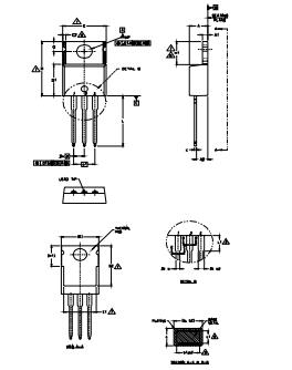
IRF1010E Package

IRF1010E Package

IRF1010E Manufacturer

On April 1, 1999, Siemens Semiconductors officially changed its name to Infineon Technologies. Infineon is a dynamic and flexible company. Success in the highly competitive and ever-changing microelectronics world is our constant goal. As the world's leading designer, manufacturer and supplier, Infineon has a wide range of products used in various microelectronics applications. Our product portfolio includes not only logic products, including digital, mixed-signal and analogue integrated circuits but also discrete semiconductor products.

Datasheet PDF

IRF1010EPBF Documents

Download datasheets and manufacturer documentation for IRF1010EPBF

Frequently Asked Questions

What is the pin configuration of IRF1010E?
It has three pins namely GATE, DRAIN and SOURCE. 3:SOURCE Normally connected to GROUND; 2:DRAIN Normally connected to LOAD; 1:GATE is Normally used as a TRIGGER to turn ON the MOSFET.
What condition to operate the IRF1010E?
Maximum voltage across DRAIN and SOURCE: 60V; Maximum continuous current allowed trough DRAIN: 81A; Maximum pulsed DRAIN current: 330A; Maximum voltage across GATE and SOURCE:20 V; Maximum Operating Temperature: 175ºC; Maximum power dissipation: 170Watt.
FAQ
What is the pin configuration of IRF1010E?
It has three pins namely GATE, DRAIN and SOURCE. 3:SOURCE Normally connected to GROUND; 2:DRAIN Normally connected to LOAD; 1:GATE is Normally used as a TRIGGER to turn ON the MOSFET.
What condition to operate the IRF1010E?
Maximum voltage across DRAIN and SOURCE: 60V; Maximum continuous current allowed trough DRAIN: 81A; Maximum pulsed DRAIN current: 330A; Maximum voltage across GATE and SOURCE:20 V; Maximum Operating Temperature: 175ºC; Maximum power dissipation: 170Watt.

TAGS

Share