ATTENTION: Due to increased demand and order volume, processing time may take an additional 1-3 business days.
HomeCommunitySubjectIRF3205 Power MOSFET: Pinout, Application and Datasheet

IRF3205 Power MOSFET: Pinout, Application and Datasheet

MOSFET N-CH 55V 110A TO-220AB Hi fellas, I am back to give you a post about electronic components.

5301

Aug 28, 2021

Geoffrey Blake

How to make 2000W inverter using 30 Mosfets IRF3205 and small transformer


MOSFET N-CH 55V 110A TO-220AB

Hi fellas, I am back to give you a post about electronic components. Today I’ll give you a detailed Introduction to IRF3205. IRF3205 is a N channel HEXFT power MOSFET transistor capable of driving the load of upto 110A with max voltage of 55V. Available in TO-220 package. In this post, I’ll cover each and everything related to this transistor, its pinout, application, datasheet and other detailed information about Infineon Technologies IRF3205.
IRF3205PBF

2000In Stock
Min.: 1 Mult.: 1
Quantity Unit Price Ext. Price
1+ $2.06837$2.07
10+ $1.95129$19.51
100+ $1.84084$184.08
500+ $1.73664$868.32
1000+ $1.63834$1638.34
Unit Price:$2.06837
Subtotal: $2.07
Looking for a better price? Want a lower wholesale price? Please send an RFQ, and we will respond immediately.
Quick Links

IRF3205 Description

IRF3205 is a N channel HEXFT power MOSFET transistor capable of driving the load of upto 110A with max voltage of 55V. Available in TO-220 package. 


This transistor can be used for both switching and amplification purposes. It is a high speed switching transistor hence can be used in applications which require high speed switching of load from one input source to another and the minimum voltage require for saturation is 2V to 4V. 


It is also capable to drive a load of upto 390A in pulse mode. Moreover when used as an amplifier it is capable to deliver upto 200 Watts due to which it is also an ideal transistor to use in high power audio amplifiers. 


The operating temperature of 175°C as well as low thermal resistance offered by this device makes it an appropriate choice to be used for power dissipation around 50 Watts along with the commercial industrial applications. 


As compared to other MOSFET, IRF3205 is different as it comes with thick oxide layer at gate terminal and cannot get damaged when exposed to high input voltage while other MOSFET can be damaged whenever they are used in circuits driving high input voltage as they are having thin oxide layer thus affecting the overall performance of that device. 

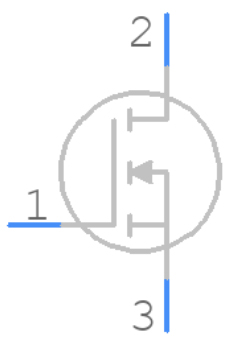
IRF3205 Pinout

IRF3205CAD Model

Symbol

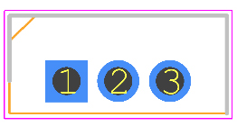
Footprint

3D Model

IRF3205 Features

●Package Type: TO-220

●Transistor Type: N Channel

●Max Voltage Applied From Drain to Source: 55V

●Max Gate to Source Voltage Should Be: ±20V

●Max Continues Drain Current is : 110A

●Max Pulsed Drain Current is: 390A

●Max Power Dissipation is: 200W

●Minimum Voltage Required to Conduct: 2V to 4V

●Max Storage & Operating temperature Should Be: -55 to +170 Centigrade

●Ultra Low On-Resistance:8 mΩ

●Fast Switching

●Advanced Process Technology.

●Fully Avalanche Rated

Specifications

Infineon Technologies IRF3205PBF technical specifications, attributes, parameters and parts with similar specifications to Infineon Technologies IRF3205PBF.

IRF3205PBF Tech Specifications

Infineon Technologies IRF3205PBF technical specifications, attributes, parameters and parts with similar specifications to Infineon Technologies IRF3205PBF.

Product Attribute Attribute Value
Factory Lead Time12 Weeks
MountThrough Hole
Mounting TypeThrough Hole
Package / CaseTO-220-3
Number of Pins3Pins
Transistor Element MaterialSILICON
Current - Continuous Drain (Id) @ 25℃110A Tc
Drive Voltage (Max Rds On, Min Rds On)10V
Number of Elements1 Element
Power Dissipation (Max)200W Tc
Turn Off Delay Time50 ns
Operating Temperature-55°C~175°C TJ
PackagingTube
SeriesHEXFET®
Published2001
Part StatusActive
Moisture Sensitivity Level (MSL)1 (Unlimited)
Number of Terminations3Terminations
TerminationThrough Hole
ECCN CodeEAR99
Product Attribute Attribute Value
Resistance8mOhm
Additional FeatureAVALANCHE RATED, HIGH RELIABILITY, ULTRA-LOW RESISTANCE
Voltage - Rated DC55V
Current Rating110A
Lead Pitch2.54mm
Number of Channels1Channel
Element ConfigurationSingle
Operating ModeENHANCEMENT MODE
Power Dissipation150W
Case ConnectionDRAIN
Turn On Delay Time14 ns
FET TypeN-Channel
Transistor ApplicationSWITCHING
Rds On (Max) @ Id, Vgs8m Ω @ 62A, 10V
Vgs(th) (Max) @ Id4V @ 250μA
Input Capacitance (Ciss) (Max) @ Vds3247pF @ 25V
Gate Charge (Qg) (Max) @ Vgs146nC @ 10V
Rise Time101ns
Vgs (Max)±20V
Fall Time (Typ)65 ns
Product Attribute Attribute Value
Continuous Drain Current (ID)110A
Threshold Voltage4V
JEDEC-95 CodeTO-220AB
Gate to Source Voltage (Vgs)20V
Drain Current-Max (Abs) (ID)75A
Drain to Source Breakdown Voltage55V
Dual Supply Voltage55V
Avalanche Energy Rating (Eas)264 mJ
Recovery Time104 ns
Max Junction Temperature (Tj)175°C
Nominal Vgs4 V
Height19.8mm
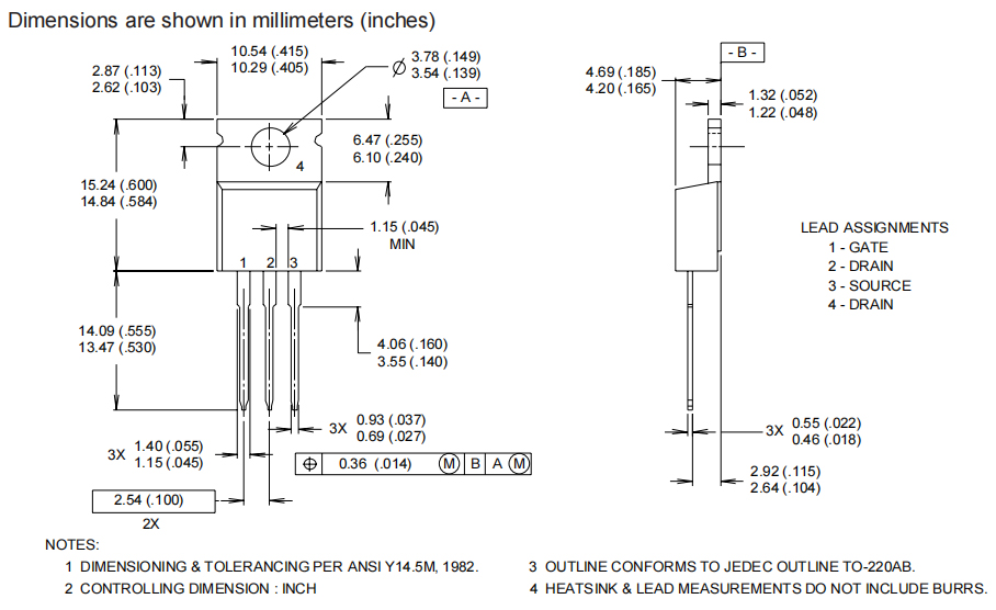
Length10.54mm
Width4.69mm
REACH SVHCNo SVHC
Radiation HardeningNo
RoHS StatusROHS3 Compliant
Lead FreeContains Lead, Lead Free
0 Products View Similar

IRF3205 Alternatives

Where to use IRF3205?

IRF3205 can be used in many applications which require high speed load switching like in UPS, Battery Backup systems etc. Other than that it can also be used in many different types of power supply applications. It can also be used to control high current loads with embedded systems. It can also be used to build high power audio amplifier circuits.


IRF3205 Applications

-Used in Consumer Full Bridge

-Used in Commercial and Industrial Applications

-Used in Full Bridge

-Used in Fast Switching Applications

-Used in Push Pull

-Used in Choppers

-Used in Speed Control

-Used in Boost Converters

-Used in Solar Inventors

-Used in Verity of Battery Chargers and Battery Management

-Used in Systems

-Used in Solar Related Applications

-Used in Uninterruptible Power Supplies

-Used in Motor Drivers

IRF3205 Package

IRF3205 Manufacturer

Infineon Technologies AG is a German semiconductor manufacturer founded in 1999, when the semiconductor operations of the former parent company Siemens AG were spun off. Infineon has about 46,665 employees and is one of the ten largest semiconductor manufacturers worldwide. It is market leader in automotive and power semiconductors.

Frequently Asked Questions

1.Can IRF3205 field tube replace IRF3710?
Can replace IRF3710 with IRF3205 But I can’t replace IRF3205 with IRF3710. The relevant parameters are as follows: Field effect tube IRF3205 parameters are (55v, 90A) The parameters of the field effect tube IRF3710 are (100v, 57A) The principle of substitution is: 1. The same as the original original; 2. The parameters of the substitute should not be less than the original parameters. If IRF3205 is broken, Available IRFK4J054 (60V 150A) IRFK4J150 (100V 137A) IRFK4J250 (200V 108A) IRFK6H150 (100V 150A) IRFK6H250 (200V 140A) ...any one to instead.
2.How much A can IRF3205 withstand instantly?
IRF3205 is: N channel, double-gate field effect tube. Parameters: 55V, 110A, 200W. Can withstand 110A instantly.
3.How to test whether IRF3205 can work?
Judge the field effect tube with an analog multi-meter. The G pole, D pole and S pole are not measured in any way. . Use an analog multimeter to hit X10K or X1K to trigger the FET and make it work. The method is: connect the black test lead to the G pole, the red test lead to the S pole, then the red test lead does not move, and the black test lead to the D pole, you will find that the FET is turned on, that is, there is a small resistance value, indicating that the tube is working normally NS. . Then connect the black test lead to the S pole, the red test lead to the G pole, and again connect the black test lead to the D pole, and the red test lead to the S pole. You will find that the FET is turned off (not working). That is, the G pole controls the on and off of the D pole and the S pole. A positive voltage is applied to the G pole, D and S are turned on, and a reverse voltage is applied to turn off. S pole and D pole have resistance. Because a diode is added to the D pole and S pole, there will be a diode characteristic. If you can't measure the diode characteristics, then the FET is broken.
FAQ
1.Can IRF3205 field tube replace IRF3710?
Can replace IRF3710 with IRF3205 But I can’t replace IRF3205 with IRF3710. The relevant parameters are as follows: Field effect tube IRF3205 parameters are (55v, 90A) The parameters of the field effect tube IRF3710 are (100v, 57A) The principle of substitution is: 1. The same as the original original; 2. The parameters of the substitute should not be less than the original parameters. If IRF3205 is broken, Available IRFK4J054 (60V 150A) IRFK4J150 (100V 137A) IRFK4J250 (200V 108A) IRFK6H150 (100V 150A) IRFK6H250 (200V 140A) ...any one to instead.
2.How much A can IRF3205 withstand instantly?
IRF3205 is: N channel, double-gate field effect tube. Parameters: 55V, 110A, 200W. Can withstand 110A instantly.
3.How to test whether IRF3205 can work?
Judge the field effect tube with an analog multi-meter. The G pole, D pole and S pole are not measured in any way. . Use an analog multimeter to hit X10K or X1K to trigger the FET and make it work. The method is: connect the black test lead to the G pole, the red test lead to the S pole, then the red test lead does not move, and the black test lead to the D pole, you will find that the FET is turned on, that is, there is a small resistance value, indicating that the tube is working normally NS. . Then connect the black test lead to the S pole, the red test lead to the G pole, and again connect the black test lead to the D pole, and the red test lead to the S pole. You will find that the FET is turned off (not working). That is, the G pole controls the on and off of the D pole and the S pole. A positive voltage is applied to the G pole, D and S are turned on, and a reverse voltage is applied to turn off. S pole and D pole have resistance. Because a diode is added to the D pole and S pole, there will be a diode characteristic. If you can't measure the diode characteristics, then the FET is broken.

TAGS

Share