Hydrogen Generator 555 Timer MOSFET IRF510 PWM
Trans MOSFET N-CH 100V 5.6A 3-Pin(3 Tab) TO-220AB
The IRF510 is a high-speed N-Channel power MOSFET with an output load capability of up to 5.6A and load voltage up to 100V.

Trans MOSFET N-CH 100V 5.6A 3-Pin(3+Tab) TO-220AB The IRF510 is a high-speed N-Channel power MOSFET with an output load capability of up to 5.6A and load voltage up to 100V.
379
Aug 1, 2021
Tabitha Keats
Hydrogen Generator 555 Timer MOSFET IRF510 PWM
Trans MOSFET N-CH 100V 5.6A 3-Pin(3 Tab) TO-220AB
The IRF510 is a high-speed N-Channel power MOSFET with an output load capability of up to 5.6A and load voltage up to 100V.
IRF510
The IRF510 is a high-speed N-Channel power MOSFET with an output load capability of up to 5.6A and load voltage up to 100V. The IRF510 power MOSFET is designed for applications such as switching regulators, switching converters, motor drivers, relay drivers, and drivers for high power bipolar switching transistors requiring high speed and low gate drive power. The IRF510 can be operated directly from integrated circuits.

Symbol
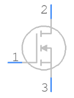
Footprint

3D Model

Package Type: TO-220
Transistor Type: N Channel
Max Voltage Applied From Drain to Source: 100 V
Max Gate to Source Voltage: ±20 V
Max Continues Drain Current: 5.6 A
Max Pulsed Drain Current: 20 A
Max Power Dissipation: 43 W
Minimum Voltage Required to Conduct: 2 V to 4 V
Max Storage & Operating temperature: -55 to +170 Celsius
Dynamic dV/dt rating
Repetitive avalanche rated
Fast switching
Ease of paralleling
Simple drive requirements
Vishay Siliconix IRF510 technical specifications, attributes, parameters and parts with similar specifications to Vishay Siliconix IRF510.
Vishay Siliconix IRF510 technical specifications, attributes, parameters and parts with similar specifications to Vishay Siliconix IRF510.
| Product Attribute | Attribute Value | |
|---|---|---|
| Mount | Through Hole | |
| Mounting Type | Through Hole | |
| Package / Case | TO-220-3 | |
| Number of Pins | 3Pins | |
| Supplier Device Package | TO-220AB | |
| Weight | 6.000006g | |
| Current - Continuous Drain (Id) @ 25℃ | 5.6A Tc | |
| Drive Voltage (Max Rds On, Min Rds On) | 10V | |
| Number of Elements | 1 Element | |
| Power Dissipation (Max) | 43W Tc | |
| Turn Off Delay Time | 15 ns | |
| Voltage - Gate Threshold (Vgs(th)) (Max) @ Id | 4V @ 250μA | |
| Operating Temperature | -55°C~175°C TJ | |
| Packaging | Tube | |
| Published | 2016 | |
| Part Status | Obsolete |
| Product Attribute | Attribute Value | |
|---|---|---|
| Moisture Sensitivity Level (MSL) | 1 (Unlimited) | |
| Max Operating Temperature | 175°C | |
| Min Operating Temperature | -55°C | |
| Voltage - Rated DC | 100V | |
| Current Rating | 5.6A | |
| Number of Channels | 1Channel | |
| Element Configuration | Single | |
| Power Dissipation | 43W | |
| Turn On Delay Time | 6.9 ns | |
| FET Type | N-Channel | |
| Rds On (Max) @ Id, Vgs | 540mOhm @ 3.4A, 10V | |
| Input Capacitance (Ciss) (Max) @ Vds | 180pF @ 25V | |
| Gate Charge (Qg) (Max) @ Vgs | 8.3nC @ 10V | |
| Rise Time | 16ns | |
| Drain to Source Voltage (Vdss) | 100V | |
| Vgs (Max) | ±20V |
| Product Attribute | Attribute Value | |
|---|---|---|
| Fall Time (Typ) | 9.4 ns | |
| Continuous Drain Current (ID) | 5.6A | |
| Gate to Source Voltage (Vgs) | 20V | |
| Drain to Source Breakdown Voltage | 100V | |
| Input Capacitance | 180pF | |
| Drain to Source Resistance | 540mOhm | |
| Rds On Max | 540 mΩ | |
| Nominal Vgs | 4 V | |
| Height | 9.01mm | |
| Length | 10.41mm | |
| Width | 4.7mm | |
| REACH SVHC | Unknown | |
| Radiation Hardening | No | |
| RoHS Status | Non-RoHS Compliant | |
| Lead Free | Contains Lead |
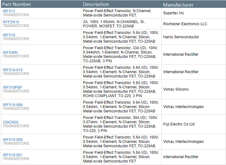
The IRF510 can be used in normal and high-speed applications such as DC to DC converters, UPS, power supplies, etc. It can drive high-power relays switches with very low power. And it can be used to drive high-power transistors or any application that requires speed switching with low gate power. What's more, due to its low gate power requirements, it can be operated directly from ICs, microcontrollers, and many electronic platforms such as Arduino, raspberry pi, etc. Other than that, it can also be used to build high-power audio amplifier circuits or be used as a separate amplifier to drive speakers.
Fast Switching
Uninterruptible Power Supplies
Battery Chargers & Management Systems
Solar Battery Chargers & Applications
Solar Uninterruptible Power Supplies
Motor Driver Circuits
Computer & telecommunication applications
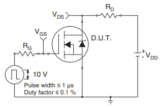
Switching Time Test Circuit
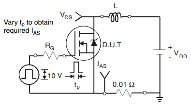
Unclamped Inductive Test Circuit
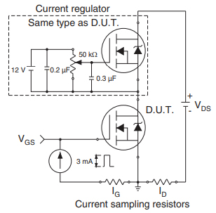
Gate Charge Test Circuit

IRF510 Package Outline

IRF510 Mechanical Data
Vishay's product portfolio is an unmatched collection of discrete semiconductors (diodes, MOSFETs, and optoelectronics) and passive components (resistors, inductors, and capacitors). These components are used in virtually all types of electronic devices and equipment in the industrial, computing, automotive, consumer, telecommunications, military, aerospace, and medical markets. Vishay is proud to be a major partner with Digi-Key.
Download datasheets and manufacturer documentation for Vishay Siliconix IRF510.
Download datasheets and manufacturer documentation for IRF510
TAGS
Comments