ATTENTION: Due to increased demand and order volume, processing time may take an additional 1-3 business days.
HomeCommunitySubjectIRF740 Power MOSFET: Replacement, Price and Circuit

IRF740 Power MOSFET: Replacement, Price and Circuit

MOSFET N-CH 400V 10A TO-220AB Hello everyone, I am Rose. Today we will have a discussion about IRF740.

890

Aug 23, 2021

Vanessa Peggy

MOSFET IRF740 (getting to know it)


MOSFET N-CH 400V 10A TO-220AB

Hello everyone, I am Rose. Today we will have a discussion about IRF740. The IRF740 is an N-channel MOSFET that comes with 125W power dissipation. This article mainly introduce replacement, price, circuit and other detailed information about Vishay Siliconix IRF740.
IRF740

Inquiry
Min.: 1 Mult.: 1
Price not displayed? Not available to buy online? Please send an RFQ, and we will respond immediately.
Quick Links

IRF740 Description

The IRF740 is an N-channel MOSFET that comes with 125W power dissipation. This is the power device dissipates during the working of this component.


This device is mainly used for fast switching and high voltage applications and comes with ultra-low on-resistance of 0.55 Ohms which is the resistance between drain and source terminals. IRF740 can also work as an amplifier and it can be used in many types of audio amplifier circuits.


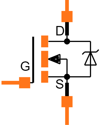
The IRF740 contains three terminals named source, drain, and gate. Sometimes it is termed as a four-pin device when the body is also considered as its terminal.


The gate terminal is located between the source and drain terminals and is the area used for biasing of the device. While the drain terminal is the location from where electrons leave the channel and the source terminal is the location from where electrons enter the channel.

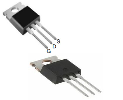
IRF740 Pinout

IRF740 has three pins, G stands for Gate, D stands for Drain, S stands for Source.

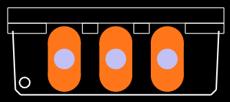
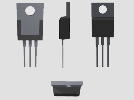
IRF740 CAD Model

Symbol

Footprint

3D Model

IRF740 Features

●N-Channel Power MOSFET

●Continuous Drain Current (ID): 10A

●Gate Threshold Voltage (VGS-th) is 10V (limit = ±20V)

●Drain to Source Breakdown Voltage: 400V

●Drain Source Resistance (RDS) is 0.55 Ohms

●Rise Time and Fall Time is 27nS and 24nS

●Available in To-220 package

●Capable of fast switching

●Power Dissipation = 125W

●Junction Temperature = 150C

●Maximum Continuous Drain Current = 10A

●Drain-Source Capacitance = 1450pF

●Max Pulsed Drain Current is: 40A

●Minimum Voltage Required to Conduct: 2V to 4V

●Max Storage & Operating Temperature Should Be: -55 to +150 Centigrade

Specifications

Vishay Siliconix IRF740 technical specifications, attributes, parameters and parts with similar specifications to Vishay Siliconix IRF740.

IRF740 Tech Specifications

Vishay Siliconix IRF740 technical specifications, attributes, parameters and parts with similar specifications to Vishay Siliconix IRF740.

Product Attribute Attribute Value
MountThrough Hole
Mounting TypeThrough Hole
Package / CaseTO-220-3
Number of Pins3Pins
Supplier Device PackageTO-220AB
Weight6.000006g
Current - Continuous Drain (Id) @ 25℃10A Tc
Drive Voltage (Max Rds On, Min Rds On)10V
Number of Elements1 Element
Power Dissipation (Max)125W Tc
Turn Off Delay Time50 ns
Operating Temperature-55°C~150°C TJ
PackagingTube
Published2012
Part StatusObsolete
Product Attribute Attribute Value
Moisture Sensitivity Level (MSL)1 (Unlimited)
Max Operating Temperature150°C
Min Operating Temperature-55°C
Voltage - Rated DC400V
Current Rating10A
Number of Channels1Channel
Element ConfigurationSingle
Power Dissipation125W
Turn On Delay Time14 ns
FET TypeN-Channel
Rds On (Max) @ Id, Vgs550mOhm @ 6A, 10V
Vgs(th) (Max) @ Id4V @ 250μA
Input Capacitance (Ciss) (Max) @ Vds1400pF @ 25V
Gate Charge (Qg) (Max) @ Vgs63nC @ 10V
Rise Time27ns
Product Attribute Attribute Value
Drain to Source Voltage (Vdss)400V
Vgs (Max)±20V
Fall Time (Typ)24 ns
Continuous Drain Current (ID)10A
Gate to Source Voltage (Vgs)20V
Drain to Source Breakdown Voltage400V
Input Capacitance1.4nF
Drain to Source Resistance550mOhm
Rds On Max550 mΩ
Height9.01mm
Length10.41mm
Width4.7mm
Radiation HardeningNo
RoHS StatusNon-RoHS Compliant
Lead FreeContains Lead
0 Products View Similar

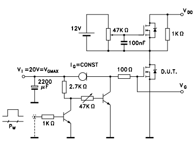
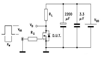
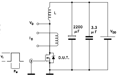
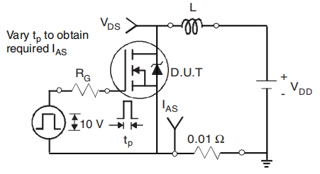
IRF740 Test Circuit

Gate Charge Test Circuit

Switching times test circuit for resistive load 

Test circuit for inductive load

Unclamped Inductive Load Test Circuit

Where to use IRF740?

IRF740 can be used in circuits in which you want to drive voltage load of upto 400V with 10A load current. Also the high speed switching capability makes it suitable in applications where user requires switching from one source to another in nanoseconds. 


The 400V load capability makes it suitable to use in variety of high voltage applications such as uninterrupted power supplies, LED and other light ballasts etc. Moreover this transistor can also be used in audio amplifier circuit stages and also as a separate audio amplifier.


IRF740 Applications

■Used in switching high power devices

■Used in inverter Circuits

■Used in DC-DC Converters

■ Used in control speed of motors

■ Used in LED dimmers or flashers

■ Used in USP

■ Used in instrumentation projects

■ Used in embedded projects

■ Used in fast switching applications

■ Used in high voltage applications

■ Used in AC motor drivers and controllers applications

■ Used in DC Motor drivers and controllers applications

■ Used in battery charger circuits

■ Used in lighting and ballast circuits

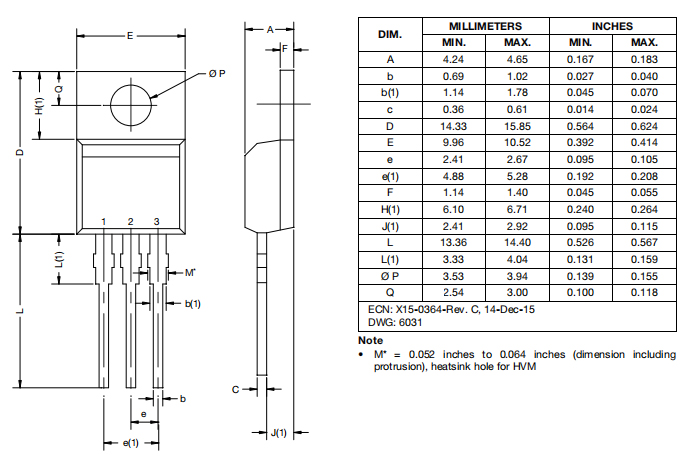
IRF740 Package

IRF740 Manufacturer

Vishay Intertechnology, Inc. is an American manufacturer of discrete semiconductors and passive electronic components founded by Polish-born businessman Felix Zandman. Vishay has manufacturing plants in Israel, Asia, Europe, and the Americas where it produces rectifiers, diodes, MOSFETs, optoelectronics, selected integrated circuits, resistors, capacitors, and inductors. 


Vishay is one of the world's foremost manufacturers of power MOSFETs. They have a wide range of power electronic applications, including portable information appliances, internet communications infrastructure, power integrated circuits, cell phones, and notebook computers.


Datasheet PDF

Download datasheets and manufacturer documentation for Vishay Siliconix IRF740.

IRF740 Documents

Download datasheets and manufacturer documentation for IRF740

Datasheets
IRF740PBF
Other Related Documents
Packaging Information
PCN Obsolescence/ EOL
SIL-018-2015-Rev-0 20/May/2015

Frequently Asked Questions

What is the difference between IRFP740 and IRF740 field effect tube?
①. Regarding IRFP740 belongs to N-MOSFET power field effect tube, its parameters are // Withstand voltage: 400V// Current: 10A//. ②. Regarding the above IRF740 belongs to N-MOSFET, power field effect tube, used for high power and high speed, such as switching power supply, UPS power supply, AC and DC motor control, relay and solenoid drive and other pulse circuits, etc., this tube parameter Yes//Withstand voltage: 400V//Current: 10A//Power: 125W//. ③ The main electrical parameters of the above two FETs are the same, there is no difference.
2.How to judge the quality of IRF740 in ultrasonic cleaning machine?
The multimeter Rxlkll blocks to measure the forward and reverse resistance values between any two pins of the field effect tube. If the resistance value is small twice or more (almost 0xkll), the field effect tube is damaged; if the resistance value is small only once (generally hundreds of ohms), the resistance value of the remaining measurements is infinite , And further judgment is needed. Use the multimeter Rxlkfl to measure the positive and negative resistance between the D pole and the S pole. For the N-channel tube, connect the red test lead to the S pole and the black test lead to touch the G pole first, and then measure the forward and reverse resistance values between the D pole and the S pole. If the measured positive and reverse resistance values are both 0fl, the tube is good. For the P-channel tube, connect the black test lead to the S pole and the red test lead to touch the G pole first, and then measure the difference between the D pole and the S pole. The forward and reverse resistance values, if the measured forward and reverse resistance values are both 01l, the tube is good. Otherwise, it is damaged.
3.Can IRF260 replace IRF740?
The VDss of the IRF260 is 200V, the RDs is 0.04 ohms, and the ID is 56A. The VDss of the IRF740 is 400V, the RDs is 0.55 ohms, and the ID is 10A. The voltage VDss is low, depending on the application, high voltage cannot be replaced.
FAQ
What is the difference between IRFP740 and IRF740 field effect tube?
①. Regarding IRFP740 belongs to N-MOSFET power field effect tube, its parameters are // Withstand voltage: 400V// Current: 10A//. ②. Regarding the above IRF740 belongs to N-MOSFET, power field effect tube, used for high power and high speed, such as switching power supply, UPS power supply, AC and DC motor control, relay and solenoid drive and other pulse circuits, etc., this tube parameter Yes//Withstand voltage: 400V//Current: 10A//Power: 125W//. ③ The main electrical parameters of the above two FETs are the same, there is no difference.
2.How to judge the quality of IRF740 in ultrasonic cleaning machine?
The multimeter Rxlkll blocks to measure the forward and reverse resistance values between any two pins of the field effect tube. If the resistance value is small twice or more (almost 0xkll), the field effect tube is damaged; if the resistance value is small only once (generally hundreds of ohms), the resistance value of the remaining measurements is infinite , And further judgment is needed. Use the multimeter Rxlkfl to measure the positive and negative resistance between the D pole and the S pole. For the N-channel tube, connect the red test lead to the S pole and the black test lead to touch the G pole first, and then measure the forward and reverse resistance values between the D pole and the S pole. If the measured positive and reverse resistance values are both 0fl, the tube is good. For the P-channel tube, connect the black test lead to the S pole and the red test lead to touch the G pole first, and then measure the difference between the D pole and the S pole. The forward and reverse resistance values, if the measured forward and reverse resistance values are both 01l, the tube is good. Otherwise, it is damaged.
3.Can IRF260 replace IRF740?
The VDss of the IRF260 is 200V, the RDs is 0.04 ohms, and the ID is 56A. The VDss of the IRF740 is 400V, the RDs is 0.55 ohms, and the ID is 10A. The voltage VDss is low, depending on the application, high voltage cannot be replaced.

TAGS

Share