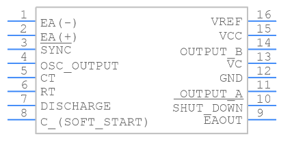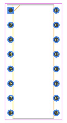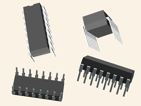
Pinout
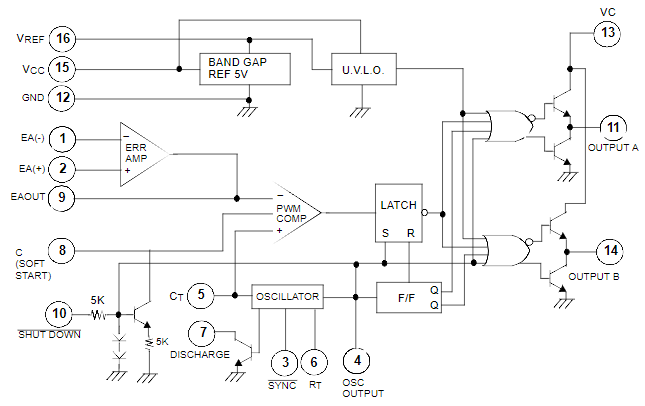
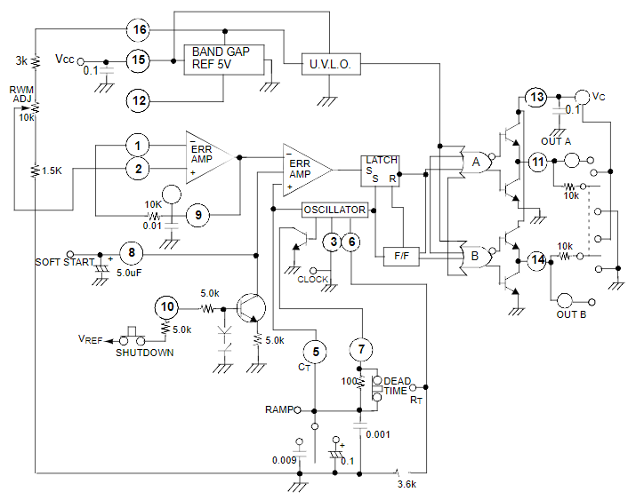
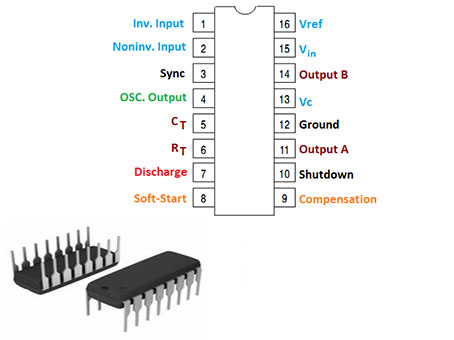
• Pin 1 is the inverting pin, while pin 2 is the non-inverting pin.
• The duty cycle increases if the voltage on the non-inverting pin is smaller than the voltage on the inverting pin.
• Pin 3 is used for the synchronization of two waves, while Pin 4 is an oscillator's output pin.
• Pins 5, 6, and 7 are used to change the PWM frequency.
• We can change the value of the discharge resistor, CT capacitor, and RT resistor to change the frequency of PWM.
• Pin 8 SS is a soft start pin that allows the output signal to be enabled after a certain amount of time. The soft-start time is directly proportional to the capacitance.
• Pin 9 is a compensation pin that is used to mitigate rapid output voltage signal swings.
• Pin 10 is referred to as the shutdown pin. When the current hits its limit, the PWM signal is turned off.
• The output pins (pins 11 and 14) are used to supply input to the MOSFETs. A MOSFET driver circuit is included into the KA3525A.
• The power pins are pins 13 and 15. Vc should be between 5 and 35 volts, while Vin should be between 8 and 35 volts.
• Pin 16 is the reference pin, which is used to modify the reference voltage via pins 1 and 2.