ATTENTION: Due to increased demand and order volume, processing time may take an additional 1-3 business days.
HomeCommunitySubjectL297 Stepper Motor Driver Controller: Datasheet, L297 and L298

L297 Stepper Motor Driver Controller: Datasheet, L297 and L298

PMIC - Motor Drivers, Controllers 20-SOIC (0.295, 7.50mm Width) General Purpose 4.75V~7V -40°C~150°C TJ 5V L297 1.27mm STMICROELECTRONICS - L297D - IC, STEPPER MOTOR CONTROLLER, SMD

180

Oct 27, 2021

Cleveland Whyet

L297 stepper controller for beginners

PMIC - Motor Drivers, Controllers 20-SOIC (0.295, 7.50mm Width) General Purpose 4.75V~7V -40°C~150°C TJ 5V L297 1.27mm STMICROELECTRONICS - L297D - IC, STEPPER MOTOR CONTROLLER, SMD

The L297 is a stepper motor controller IC. This post will unlock more details about L297. There is a huge range of Semiconductors, Capacitors, Resistors and ICs in stock. Welcome RFQ.

L297D

93In Stock
Min.: 1 Mult.: 1
Quantity Unit Price Ext. Price
1+ $29.2849$29.28
10+ $27.62726$276.27
100+ $26.06346$2606.35
500+ $24.58817$12294.09
1000+ $23.19638$23196.38
Unit Price:$29.2849
Subtotal: $29.28
Looking for a better price? Want a lower wholesale price? Please send an RFQ, and we will respond immediately.
Quick Links

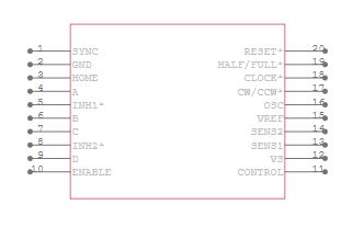
L297 Pinout

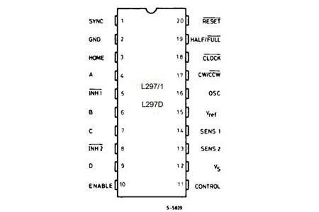
L297 Pinout

L297 CAD Model

Symbol

L297 Symbol

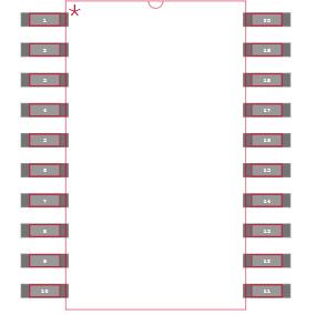
Footprint

L297 Footprint

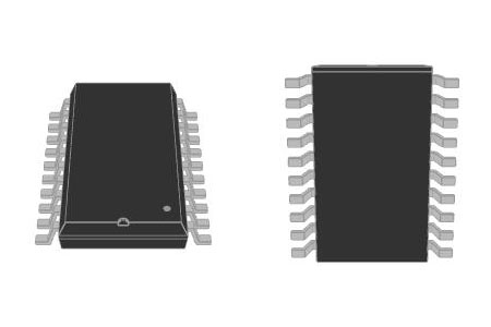
3D Model

L297 3D Model

L297 Description

The L297 Stepper Motor Controller IC generates four phase drive signals for two-phase bipolar and four-phase unipolar step motors in microcomputer-controlled applications. The motor can be driven in half step, normal and wave drive modes and on-chip PWM chopper circuits permit switch-mode control of the current in the windings. A feature of this device is that it requires only clock, direction and mode input signals. Since the phase is generated internally the burden on the microprocessor, and the programmer is greatly reduced. Mounted in DIP20 and SO20 packages, the L297 can be used with monolithic bridge drives such as the L298N or L293E, or with discrete transistors and Darlington.

L297 Feature

  • Normal/ wave drive

  • Half/ full step modes

  • Clockwise/ anticlockwise direction

  • Switchmode load current regulation

  • Programmable load current

  • Few external components

  • Reset input&home output

  • Enable input

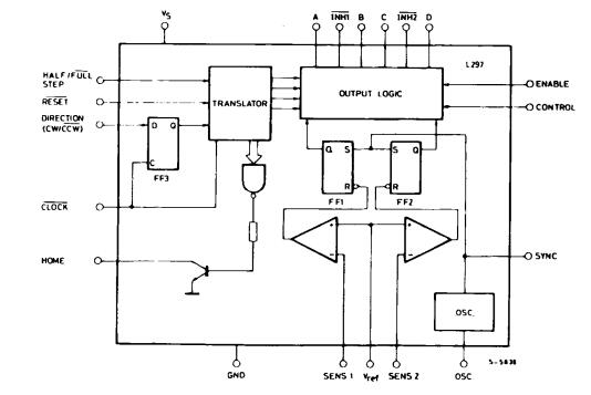
L297 Schematic

L297 Schematic

L297 and L298 Circuit

A two-phase bipolar stepper motor drive circuit can be built using L297 and L298. It's powered by a constant current mode, and each phase's peak current can reach 2A. The L297 is a stepper motor controller that produces two-phase bipolar voltage. Set the drive signal (A, B, C, D) and the motor current. The stepper motor's power output is driven by the L298. A double full bridge mode is used to power it. The motor coil is fully utilized due to the bipolar drive, allowing the motor to attain the best drive.

A stepping motor subdivision driving circuit is constructed when two pieces of L297 are used to drive the two windings of a stepping motor through L298, and the Vref corresponding to each winding is adjusted through two D/A converters.

The schematic below depicts the L297+L298 drive wiring theory. The appropriate control terminals of L297 are linked to ports P0 and P4. The goal of commanding the motor to rotate in the predicted direction is therefore accomplished thanks to the software's rational organization.
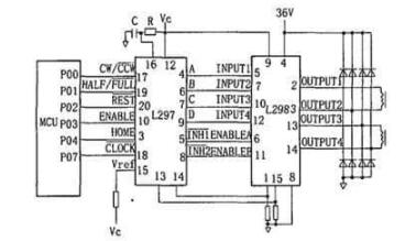
L297 and L298 Schematic Diagram

In addition, terminal 1 of L297 is the synchronous terminal, which can be connected to terminal 1 of another group of L297 and L298 drive circuits. In this way, the two sets of drivers can be synchronized to achieve the effect of driving multiple motors at the same time.
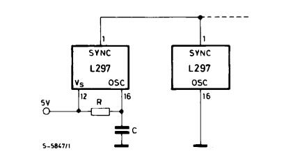
Synchronising L297s

Specifications

L297D Tech Specifications

STMicroelectronics L297D technical specifications, attributes, parameters and parts with similar specifications to STMicroelectronics L297D.

Product Attribute Attribute Value
Lifecycle StatusACTIVE (Last Updated: 7 months ago)
Factory Lead Time10 Weeks
MountSurface Mount
Mounting TypeSurface Mount
Package / Case20-SOIC (0.295, 7.50mm Width)
Number of Pins20Pins
Operating Temperature-40°C~150°C TJ
PackagingTube
JESD-609 Codee4
Part StatusActive
Moisture Sensitivity Level (MSL)3 (168 Hours)
Number of Terminations20Terminations
ECCN CodeEAR99
Terminal FinishNickel/Palladium/Gold (Ni/Pd/Au)
ApplicationsGeneral Purpose
Product Attribute Attribute Value
Voltage - Supply4.75V~7V
Terminal PositionDUAL
Terminal FormGULL WING
Peak Reflow Temperature (Cel)260
Supply Voltage5V
Terminal Pitch1.27mm
Time@Peak Reflow Temperature-Max (s)30
Base Part NumberL297
FunctionController - Commutation, Direction Management
Number of Outputs4Outputs
Output Voltage3.9V
Operating Supply Voltage5V
Supply Voltage-Max (Vsup)7V
Power Supplies5V
InterfaceParallel
Product Attribute Attribute Value
Nominal Supply Current80mA
Output ConfigurationPre-Driver - Half Bridge (4)
Output Current10mA
Collector Emitter Voltage (VCEO)7V
Motor TypeStepper
Motor Type - StepperBipolar, Unipolar
Step Resolution1, 1/2
Height2.35mm
Length13mm
Width7.6mm
REACH SVHCNo SVHC
Radiation HardeningNo
RoHS StatusROHS3 Compliant
Lead FreeLead Free
0 Products View Similar

L297 Package

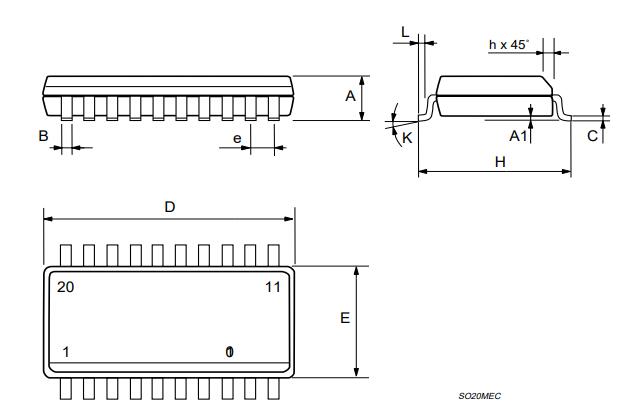
L297 Package

L297 Manufacturer

STMicroelectronics is a globally recognized semiconductor company. They are dedicated to developing semiconductor solutions for various microelectronics applications. STMicroelectronics enjoys unrivalled silicon and system expertise, strong manufacturing strength, IP portfolio, and solid relationships with their strategic partners. Based on these advantages, STMicroelectronics has become a pioneer in System-on-Chip (SoC) technology and its products have a positive effect in realizing today's convergence trends.

Datasheet PDF

L297D Documents

Download datasheets and manufacturer documentation for L297D

Frequently Asked Questions

What is L297?
The L297 has all of the necessary control circuits for bipolar and unipolar stepper motor control. The L298N, when combined with a dual bridge driver, creates a comprehensive microprocessor-to-bipolar stepper motor interface.
How does l298n control DC motor speed?
1. If you send a HIGH signal to the enable 1 pin, motor A is ready to be controlled and at the maximum speed; 2. If you send a LOW signal to the enable 1 pin, motor A turns off; 3. If you send a PWM signal, you can control the speed of the motor. The motor speed is proportional to the duty
What is the motor driving phase sequences of L297?
The L297’s translator generates phase sequences for a normal drive, wave drive and half step modes. The state sequences and output waveforms for these three modes are shown below. In all cases, the translator advances on the low to high transition of CLOCK. Clockwise rotation is indicated; for anticlockwise rotation, the sequences are simply reversed RESET restores the translator to state 1, where ABCD = 0101.
What is the function of H bridge?
An H-bridge is an electronic circuit that switches the polarity of a voltage applied to a load. These circuits are often used in robotics and other applications to allow DC motors to run forwards or backwards.
FAQ
What is L297?
The L297 has all of the necessary control circuits for bipolar and unipolar stepper motor control. The L298N, when combined with a dual bridge driver, creates a comprehensive microprocessor-to-bipolar stepper motor interface.
How does l298n control DC motor speed?
1. If you send a HIGH signal to the enable 1 pin, motor A is ready to be controlled and at the maximum speed; 2. If you send a LOW signal to the enable 1 pin, motor A turns off; 3. If you send a PWM signal, you can control the speed of the motor. The motor speed is proportional to the duty
What is the motor driving phase sequences of L297?
The L297’s translator generates phase sequences for a normal drive, wave drive and half step modes. The state sequences and output waveforms for these three modes are shown below. In all cases, the translator advances on the low to high transition of CLOCK. Clockwise rotation is indicated; for anticlockwise rotation, the sequences are simply reversed RESET restores the translator to state 1, where ABCD = 0101.
What is the function of H bridge?
An H-bridge is an electronic circuit that switches the polarity of a voltage applied to a load. These circuits are often used in robotics and other applications to allow DC motors to run forwards or backwards.

TAGS

Share