ATTENTION: Due to increased demand and order volume, processing time may take an additional 1-3 business days.
HomeCommunitySubjectL9110S 2-Channel Motor driver: Circuit, Pinout, and How to work [Video&FAQ]

L9110S 2-Channel Motor driver: Circuit, Pinout, and How to work [Video&FAQ]

The L9110S 2-Channel motor driver module is a tiny board for controlling small robots. This article mainly introduces Circuit, Pinout, How to work and other detailed information about 2-Channel Motor driver L9110S.

5324

Apr 30, 2022

Ruth Bertie

1

How to control 2 DC motors using L9110s motor driver module with Arduino code


The L9110S 2-Channel motor driver module is a tiny board for controlling small robots. This article mainly introduces Circuit, Pinout, How to work and other detailed information about 2-Channel Motor driver L9110S.

L9110S

52192In Stock
Min.: 1 Mult.: 1
Quantity Unit Price Ext. Price
1+ $0.30022$0.3
10+ $0.28323$2.83
100+ $0.2672$26.72
500+ $0.25207$126.04
1000+ $0.2378$237.8
Unit Price:$0.30022
Subtotal: $0.3
Looking for a better price? Want a lower wholesale price? Please send an RFQ, and we will respond immediately.
Quick Links

L9110S Description

The L9110S 2-Channel motor driver module is a tiny board for controlling small robots. This module contains two motor driver chips, each capable of driving up to 800mA of continuous current. The boards may function between 2.5 and 12 volts, allowing this module to work with both 3.3 and 5-volt microcontrollers.

This module is connected to a microcontroller through a set of female header pins. Two sets of screw terminals are used to connect the motors.

A PWM (Pulse Width Modulation) signal is used to control a motor's speed, while a digital output is utilized to modify its direction. A single four-line two-phase stepper motor can also be driven with this module. This board has four holes that make it simple to attach to your robot or other projects.

• Two independent L9110S  motor driver chips 

• 800mA continuous current per channel

• Can drive two bidirectional DC motors or a four-line two-phase stepper motor 

• Four mounting holes

L9110S Pin Configuration

The following shows L9110S Pin Configuration.

Pin Configuration


Pin Number Pin Name Description
1 B-IA Motor B Input A
2 B-IB Motor B Input B
3 GND ground
4 VCC 2.5V-12V DC
5 A-IA Motor A Input A
6 A-IB Motor B Input B


More detailed information is given below.

Pinout

L9110S Features

Motor driver modules are frequently used to control the speed and direction of motors nowadays. One of them is the L9110S dual-channel module. Two  DC  motors and one stepper motor can be controlled using this module. It is based on the L9110 integrated circuit. The following are the main characteristics:

• The allowable continuous current for each channel: 800 mA

• The maximum allowable current: 1.5 A

• Power supply: 2.5V to 12V

• Low quiescent current

• 800mA continuous current output capability per channel

• Lower saturation voltage

• TTL / CMOS output level compatible, and can be directly connected to the CPU

• Output built-in clamp diodes for inductive load

• Integrated control and drive into a monolithic IC

• With pin high-voltage protection function

• Operating temperature: 0 ℃ -80 ℃


Specifications

Wuxi I-core Elec L9110S technical specifications, attributes, parameters and parts with similar specifications to Wuxi I-core Elec L9110S.

L9110S Tech Specifications

Wuxi I-core Elec L9110S technical specifications, attributes, parameters and parts with similar specifications to Wuxi I-core Elec L9110S.

Product Attribute Attribute Value
Package / CaseSOP-8_150mil
Product Attribute Attribute Value
PackagingTube-packed
Product Attribute Attribute Value
RoHS StatusRoHS Compliant
0 Products View Similar

Interfacing L9110S Dual-Channel Driver Module with Arduino

The diagram below shows how to link Arduino to these modules. Connect the wires in the proper order.

Diagram


L9110S Schematic Diagram

The L9110S Schematic Diagram is shown as follows.

Schematic Diagram

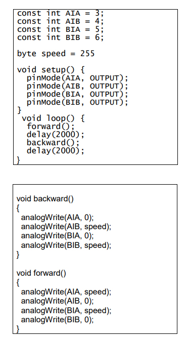
L9110S Sample Sketch

L9110S Sample Sketch

Sample Sketch


How to Test

The components to be used are:

• Microcontroller (any compatible arduino)

• L9110 2-channel motor driver

• Pin connectors

• DC motors

• 2.5V-12V DC external power supply

1. Use pin connectors to connect the components. The VCC pin is connected to a 2.5V12V DC external power source capable of handling 800mA, the GND pin to the GND, and the A-IA, A-IB  , B-IA, and B-IB  pins to the digital I/O ports. The pin number will be determined by the program code.

2. After the hardware is connected, open the Arduino IDE  and load the sample sketch.

3. Connect the microcontroller's ports to the PC with a USB connection.

4. Put the application on the computer.

L9110S Testing Results

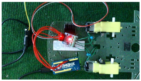
The two motors should travel forward and backward every two seconds, according to the program. Depending on the wire connections, the orientation may change.

Program

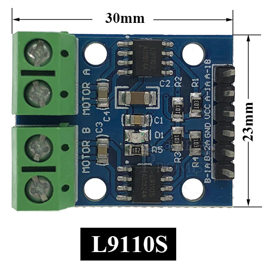
L9110S Dimension

The following shows L9110S Dimension.

Dimension

Frequently Asked Questions

What is L9110S motor driver?
The L9110S 2-Channel motor driver module is a compact board that can be used to drive small robots. This module has two independent motor driver chips which can each drive up to 800mA of continuous current. The boards can be operated from 2.5V to 12V enabling this module to be used with both 3.3V and 5V microcontrollers.
What is a motor driver IC?
A motor driver IC is an integrated circuit chip that is usually used to control motors in autonomous robots. Motor driver ICs act as an interface between microprocessors in robots and the motors in the robot.
What is a tiny board for controlling small robots?
L9110S 2-Channel motor driver module.
How many motor driver chips does the L9110S 2-Channel module contain?
Two.
How many volts can the L9110S 2-Channel motor driver chips function?
2.5 and 12 volts.
How is the L9110S 2-Channel motor driver module connected to a microcontroller?
Through a set of female header pins.
How many screw terminals are used to connect the motors?
Two sets of screw terminals.
What signal is used to control a motors speed?
PWM (Pulse Width Modulation).
What type of motor can be driven with the L9110S 2-Channel motor driver module?
Four-line two-phase stepper motor.
How many holes does the L9110S 2-Channel motor driver module have?
Four holes.
How many mounting holes does the L9110S 2-Channel motor driver module have?
Four mounting holes.
FAQ
What is L9110S motor driver?
The L9110S 2-Channel motor driver module is a compact board that can be used to drive small robots. This module has two independent motor driver chips which can each drive up to 800mA of continuous current. The boards can be operated from 2.5V to 12V enabling this module to be used with both 3.3V and 5V microcontrollers.
What is a motor driver IC?
A motor driver IC is an integrated circuit chip that is usually used to control motors in autonomous robots. Motor driver ICs act as an interface between microprocessors in robots and the motors in the robot.
What is a tiny board for controlling small robots?
L9110S 2-Channel motor driver module.
How many motor driver chips does the L9110S 2-Channel module contain?
Two.
How many volts can the L9110S 2-Channel motor driver chips function?
2.5 and 12 volts.
How is the L9110S 2-Channel motor driver module connected to a microcontroller?
Through a set of female header pins.
How many screw terminals are used to connect the motors?
Two sets of screw terminals.
What signal is used to control a motors speed?
PWM (Pulse Width Modulation).
What type of motor can be driven with the L9110S 2-Channel motor driver module?
Four-line two-phase stepper motor.
How many holes does the L9110S 2-Channel motor driver module have?
Four holes.
How many mounting holes does the L9110S 2-Channel motor driver module have?
Four mounting holes.

TAGS

Share