ATTENTION: Due to increased demand and order volume, processing time may take an additional 1-3 business days.
HomeCommunitySubjectLF356 op-amp: Package, Pinout and Datasheet

LF356 op-amp: Package, Pinout and Datasheet

IC OPAMP JFET 1 CIRCUIT 8DIP LF356 is the first monolithic JFET input operational amplifiers to incorporate well matched, high voltage JFETs on the same chip with standard bipolar transistors. This article is about its package, pinout,datasheet PDF and other detailed information.
655

Jun 16, 2021

Joanne

Simulation Schmitt trigger circuit using Op-amp LF356


IC OPAMP JFET 1 CIRCUIT 8DIP

LF356 is the first monolithic JFET input operational amplifiers to incorporate well matched, high voltage JFETs on the same chip with standard bipolar transistors. This article is about its package, pinout,datasheet PDF and other detailed information.
LF356N

2000In Stock
Min.: 1 Mult.: 1
Price not displayed? Not available to buy online? Please send an RFQ, and we will respond immediately.
Quick Links

LF356N Description

The LF356N is one of the first monolithic JFET input operational amplifiers to incorporate well-matched, high voltage JFETs on the same chip with standard bipolar transistors (BI-FET™ Technology). The LF356N features low input bias and offset currents/low offset voltage and offset voltage drift, coupled with offset adjust which does not degrade drift or common-mode rejection. The LF356N is also designed for high slew rate, wide bandwidth, extremely fast settling time, low voltage and current noise, and a low 1/f noise corner.

LF356 CAD Model

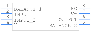
Symbol

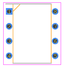
Footprint

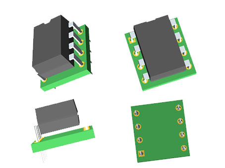
3D Model

LF356 Features

-Replace expensive hybrid and module FET op amps

-Rugged JFETs allow blow-out free handling compared with MOSFET input devices

-Excellent for low noise applications using either high or low source impedance — very low 1/f corner

-Offset adjust does not degrade drift or common-mode rejection as in most monolithic amplifiers

-New output stage allows use of large capacitive loads (5,000 pF) without stability problems

-Internal compensation and large differential input voltage capability


Specifications

Texas Instruments LF356N technical specifications, attributes, parameters and parts with similar specifications to Texas Instruments LF356N.

LF356N Tech Specifications

Texas Instruments LF356N technical specifications, attributes, parameters and parts with similar specifications to Texas Instruments LF356N.

Product Attribute Attribute Value
MountThrough Hole
Mounting TypeThrough Hole
Package / Case8-DIP (0.300, 7.62mm)
Number of Pins8Pins
Operating Temperature0°C~70°C
PackagingTube
SeriesBI-FET™
JESD-609 Codee0
Pbfree Codeno
Part StatusObsolete
Moisture Sensitivity Level (MSL)1 (Unlimited)
Number of Terminations8Terminations
ECCN CodeEAR99
Terminal FinishTin/Lead (Sn/Pb)
Packing MethodRAIL
Max Power Dissipation670mW
Terminal PositionDUAL
Number of Functions1Function
Product Attribute Attribute Value
Supply Voltage15V
Terminal Pitch2.54mm
Base Part NumberLF356
Pin Count8
Operating Supply Voltage15V
Number of Channels1Channel
Operating Supply Current5mA
Nominal Supply Current5mA
Power Dissipation670mW
Output Current25mA
Max Supply Current10mA
Slew Rate12V/μs
ArchitectureVOLTAGE-FEEDBACK
Amplifier TypeJ-FET
Common Mode Rejection Ratio80 dB
Current - Input Bias30pA
Voltage - Supply, Single/Dual (±)±15V
Input Offset Voltage (Vos)10mV
Product Attribute Attribute Value
Neg Supply Voltage-Nom (Vsup)-15V
Unity Gain BW-Nom5000 kHz
Voltage Gain106.02dB
Average Bias Current-Max (IIB)0.0002μA
Power Supply Rejection Ratio (PSRR)80dB
Low-OffsetNO
Frequency CompensationYES
Voltage - Input Offset3mV
Low-BiasYES
Bias Current-Max (IIB) @25C0.0002μA
Input Offset Current-Max (IIO)0.002μA
Height3.3mm
Length9.27mm
Width6.35mm
REACH SVHCNo SVHC
Radiation HardeningNo
RoHS StatusNon-RoHS Compliant
Lead FreeContains Lead
0 Products View Similar

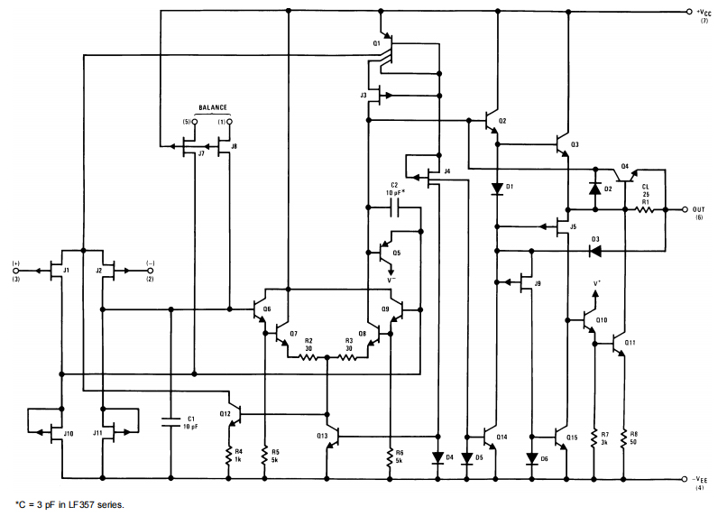
LF356 Functional Block Diagram

LF356 Application

-Precision high speed integrators

-Fast D/A and A/D converters

-High impedance buffers

-Wideband, low noise, low drift amplifiers

-Logarithmic amplifiers

-Photocell amplifiers

-Sample and Hold circuits

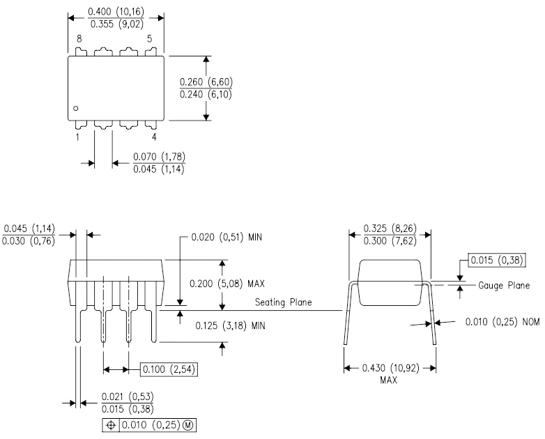
LF356 Package

LF356 Manufacturer

As a global semiconductor company operating in 35 countries, Texas Instruments (TI) is first and foremost a reflection of its people. From the TIer who unveiled the first working integrated circuit in 1958 to the more than 30,000 TIers around the world today who design, manufacture and sell analog and embedded processing chips, we are problem-solvers collaborating to change the world through technology.


Datasheet PDF

Download datasheets and manufacturer documentation for Texas Instruments LF356N.

LF356N Documents

Download datasheets and manufacturer documentation for LF356N

Frequently Asked Questions

1.In terms of the imperfections, what op-amp (the LM741 or the LF356) is closest to an ideal op-amp, and why?
The ‘356 has several things going for it that the 741 doesn’t have. It uses FET inputs, so the current going into the chip is greatly reduced. The slew rate of the 356 is also better. This means it can reproduce higher frequencies at a higher voltage level than the 741.Generally speaking, those two specs, input impedance and slew rate output are the most important. I would take the LF356 for nearly anything if I had to choose one.
2.How can I get the maximum output voltage of an op-amp knowing the input voltage, specifically an LF356?
The maximum output voltage is dependent on the input voltage, the gain set by external components, supply voltage and the output voltage swing as in the datasheet. With the LF356 it is +-13V of a +-15V supply into 10k or +-12V at 2 kilohms output load.
3.Why isn't my LF356 op-amp rail-to-rail? Even if the load impedance is 10M ohm, the output voltage is like a volt off.
The LF356 is not capable of rail-to-rail output swing because of its output stage design. The portion of the circuit that handles the positive-going parts of the signal consists of two NPN transistors in a Darlington arrangement. This results in a voltage drop that is twice the base-emitter drop associated with the process used to manufacture this integrated circuit. For silicon processes, that is about 0.65 V per junction or 1.3 V for a Darlington.
4.Which op-amp (the LM741 or LF356) is better suited for high-frequency signals in terms of bandwidth?
LF356 has a GBW of 5MHz and LM741 has a GBW of 1MHz. So In this aspect is the LF356 better. BUT they are both very old designs, and if you do no need the high operating voltage range, use a more modern OP-AMP.

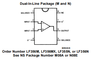
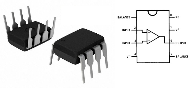
LF356N Pinout

FAQ
1.In terms of the imperfections, what op-amp (the LM741 or the LF356) is closest to an ideal op-amp, and why?
The ‘356 has several things going for it that the 741 doesn’t have. It uses FET inputs, so the current going into the chip is greatly reduced. The slew rate of the 356 is also better. This means it can reproduce higher frequencies at a higher voltage level than the 741.Generally speaking, those two specs, input impedance and slew rate output are the most important. I would take the LF356 for nearly anything if I had to choose one.
2.How can I get the maximum output voltage of an op-amp knowing the input voltage, specifically an LF356?
The maximum output voltage is dependent on the input voltage, the gain set by external components, supply voltage and the output voltage swing as in the datasheet. With the LF356 it is +-13V of a +-15V supply into 10k or +-12V at 2 kilohms output load.
3.Why isn't my LF356 op-amp rail-to-rail? Even if the load impedance is 10M ohm, the output voltage is like a volt off.
The LF356 is not capable of rail-to-rail output swing because of its output stage design. The portion of the circuit that handles the positive-going parts of the signal consists of two NPN transistors in a Darlington arrangement. This results in a voltage drop that is twice the base-emitter drop associated with the process used to manufacture this integrated circuit. For silicon processes, that is about 0.65 V per junction or 1.3 V for a Darlington.
4.Which op-amp (the LM741 or LF356) is better suited for high-frequency signals in terms of bandwidth?
LF356 has a GBW of 5MHz and LM741 has a GBW of 1MHz. So In this aspect is the LF356 better. BUT they are both very old designs, and if you do no need the high operating voltage range, use a more modern OP-AMP.

TAGS

Share