ATTENTION: Due to increased demand and order volume, processing time may take an additional 1-3 business days.
HomeCommunitySubjectLM1117 Voltage Regulator: Pinout, Equivalents, Datasheets Kimna

LM1117 Voltage Regulator: Pinout, Equivalents, Datasheets Kimna

IC REG LINEAR 3.3V 800MA TO220-3 The LM1117 is a low dropout voltage regulator with a dropout of 1.2V at 800 MA of load current. This article introduces pinout, Features,

699

Jun 27, 2021

Jacob Clarissa

1117, 3.3V Voltage Regulator IC : Tutorial 10


IC REG LINEAR 3.3V 800MA TO220-3

The LM1117 is a low dropout voltage regulator with a dropout of 1.2V at 800 MA of load current. This article introduces pinout, Features, CAD Model and other detail information of LM1117.

LM1117T-3.3

26200In Stock
Min.: 1 Mult.: 1
Price not displayed? Not available to buy online? Please send an RFQ, and we will respond immediately.
Quick Links

LM1117 Description

The LM1117 is a low dropout voltage regulator with a dropout of 1.2V at 800 MA of load current. The LM1117 is available in an adjustable version, which can set the output voltage from 1.25 to 13.8 V with only two external resistors.

LM1117 Pinout

LM1117 CAD Model

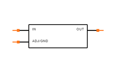
Symbol


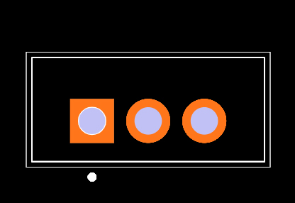
Footprint


3D Model

LM1117 Features

• Available in 1.8 V, 2.5 V, 3.3 V, 5 V, and Adjustable Versions

• Space-Saving SOT-223 and WSON Packages

• Current Limiting and Thermal Protection

• Output Current 800 mA

• Line Regulation 0.2% (Maximum)

• Load Regulation 0.4% (Maximum)

• Temperature Range

 – LM1117: 0°C to 125°C to within ±1%.

 – LM1117I: −40°C to 125°C

Specifications

Texas Instruments LM1117T-3.3 technical specifications, attributes, parameters and parts with similar specifications to Texas Instruments LM1117T-3.3.

LM1117T-3.3 Tech Specifications

Texas Instruments LM1117T-3.3 technical specifications, attributes, parameters and parts with similar specifications to Texas Instruments LM1117T-3.3.

Product Attribute Attribute Value
MountThrough Hole
Mounting TypeThrough Hole
Package / CaseTO-220-3
Number of Pins3Pins
Operating Temperature0°C~125°C
PackagingTube
SeriesLM1117-3.3
JESD-609 Codee0
Pbfree Codeno
Part StatusObsolete
Moisture Sensitivity Level (MSL)1 (Unlimited)
Number of Terminations3Terminations
ECCN CodeEAR99
Terminal FinishTin/Lead (Sn/Pb)
Product Attribute Attribute Value
Terminal PositionSINGLE
Number of Functions1Function
Terminal Pitch2.54mm
Current Rating800A
Base Part NumberLM1117
Current - Supply (Max)10mA
Number of Outputs1Output
Voltage - Input (Max)15V
Output TypeFixed
Current - Output (Max)800mA
Output ConfigurationPositive
Quiescent Current5mA
Accuracy1 %
Voltage - Output3.3V
Product Attribute Attribute Value
Output Voltage 13.3V
Number of Regulators1Regulator
Protection FeaturesOver Current, Over Temperature
Voltage Dropout (Max)1.2V @ 800mA
PSRR75dB (120Hz)
Dropout Voltage1.2V
Dropout Voltage1-Nom1.2V
Voltage Tolerance-Max2%
Min Current Limit800mA
Nominal Output Voltage3.3V
Output Voltage Accuracy1 %
REACH SVHCNo SVHC
Radiation HardeningNo
RoHS StatusNon-RoHS Compliant
0 Products View Similar

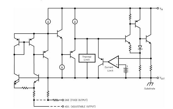
LM1117 Functional Block Diagram

Where to use LM1117

Just like the famous 7805 and LM317, the LM1117 is another Linear Voltage regulator. It is known for its small form factor since it is available as a DCY Package (SMD Component). There are many types of LM1117, the fixed types provide a fixed output voltage of 1.8V, 2.5V, 3.3V or 5V and the variable voltage regulator can have a variable voltage from 1.25V to 13.8V.

So if you are looking for a SMD component voltage regulator then this IC might be the right choice for you.

How to use LM1117

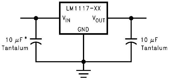
Using the LM1117 is pretty much straight forward. If it a fixed voltage regulator just power the IC though the Vin pin and the regulated output can be obtained in the Vout pin. The Adj/Ground pin in this case acts only as a ground pin and is grounded. Also a capacitor can be added at the output side to filter out the noise. The circuit diagram for a fixed output regulator is show below
For an Adjustable type voltage regulator we need two external resistors to decide the output voltage of the Regulator. A reference circuit diagram is shown below, where the resistors R1 and R2 decides the output voltage of the regulator. The capacitor CAdj is an optional component which can be added to improve ripple rejection if required. The other two capacitors are to filter the input and output noise respectively.
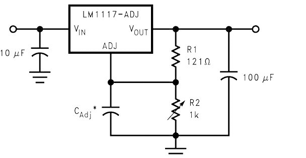
The formulae to calculate the output voltage of the regulator is given below. Select the value of R1 and R2 based on the output voltage required for your project. Keep in mind that the value of R1 should be less than 1k. You can use a variable resistor at R2 if you want to vary the voltage in real time.

VOUT = 1.25 × (1 + (R2/R1))

With the ability to be used as a fixed voltage or a variable voltage regulator the LM1117 often finds its application in battery charging circuit and can also be designed to provide negative voltage if required. Refer the datasheet at the end of this page to find more application circuits for this IC.


LM1117 Application

• Post Regulator for Switching DC–DC Converter1

• High Efficiency Linear Regulators

• Battery Chargers

• Portable Instrumentation

• Active SCSI Termination Regulator

LM1117 Dimension

LM1117 Manufacturer

As a global semiconductor company operating in 35 countries, Texas Instruments (TI) is first and foremost a reflection of its people. From the TIer who unveiled the first working integrated circuit in 1958 to the more than 30,000 TIers around the world today who design, manufacture and sell analog and embedded processing chips, Texas Instruments are problem-solvers collaborating to change the world through technology.

Datasheet PDF

Download datasheets and manufacturer documentation for Texas Instruments LM1117T-3.3.

LM1117T-3.3 Documents

Download datasheets and manufacturer documentation for LM1117T-3.3

Frequently Asked Questions

How to distinguish the LM1117 with the AMS1117?
The LM1117 has a different pinout than the previous two. The AMS1117 in addition to being of a different format, maintains compatibility with the LM1117 in terms of pins. It is a more recent integrated chip than the previous ones and with a superior efficiency.
How to connect LM1117?
To set up, attach one capacitor from the output pin of the LM1117 to the ground pin of the LM1117. Next, do the same going from the input pin to the ground pin. These capacitors are polarized. Ensure the positive leg of the capacitor is in the input/ output and the negative leg is connected to ground.
FAQ
How to distinguish the LM1117 with the AMS1117?
The LM1117 has a different pinout than the previous two. The AMS1117 in addition to being of a different format, maintains compatibility with the LM1117 in terms of pins. It is a more recent integrated chip than the previous ones and with a superior efficiency.
How to connect LM1117?
To set up, attach one capacitor from the output pin of the LM1117 to the ground pin of the LM1117. Next, do the same going from the input pin to the ground pin. These capacitors are polarized. Ensure the positive leg of the capacitor is in the input/ output and the negative leg is connected to ground.

TAGS

Share