LM3914 vs LM3915 vs LM3916 - What are the differences?
The LM3914N is an 18-pin dot/bar display driver. This article focuses on the LM3914N datasheet, pinout, applications, circuit, and other features.

IC DRVR DOT/BAR DISPLAY 18DIP The LM3914N is an 18-pin dot/bar display driver.
122
Jul 30, 2021
Rachel Gilbert
LM3914 vs LM3915 vs LM3916 - What are the differences?
The LM3914N is an 18-pin dot/bar display driver. This article focuses on the LM3914N datasheet, pinout, applications, circuit, and other features.
LM3914N-1

The LM3914N is a monolithic integrated circuit that senses analog voltage levels and drives 10 LEDs, providing a linear analog display. The circuit can drive LEDs of many colors, or low-current incandescent lamps. Many LM3914N can be “chained” to form displays of 20 to over 100 segments.
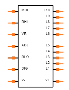
Symbol
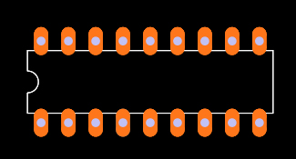
Footprint
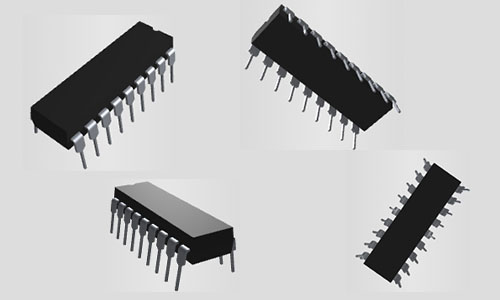
3D Model
Texas Instruments LM3914N-1 technical specifications, attributes, parameters and parts with similar specifications to Texas Instruments LM3914N-1.
Texas Instruments LM3914N-1 technical specifications, attributes, parameters and parts with similar specifications to Texas Instruments LM3914N-1.
| Product Attribute | Attribute Value | |
|---|---|---|
| Mount | Surface Mount, Through Hole | |
| Mounting Type | Through Hole | |
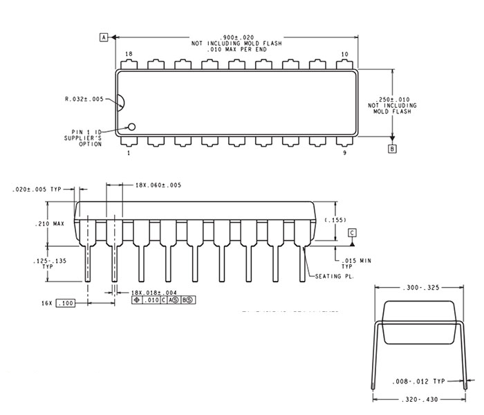
| Package / Case | 18-DIP (0.300, 7.62mm) | |
| Number of Pins | 18Pins | |
| Operating Temperature | 0°C~70°C | |
| Packaging | Tube | |
| JESD-609 Code | e0 | |
| Part Status | Obsolete | |
| Moisture Sensitivity Level (MSL) | 1 (Unlimited) | |
| Number of Terminations | 18Terminations | |
| Termination | Through Hole | |
| ECCN Code | EAR99 | |
| Terminal Finish | Tin/Lead (Sn/Pb) | |
| Additional Feature | SELECTABLE DOT MODE | |
| HTS Code | 8542.39.00.01 | |
| Max Power Dissipation | 1.365W |
| Product Attribute | Attribute Value | |
|---|---|---|
| Voltage - Supply | 3V~20V | |
| Terminal Position | DUAL | |
| Peak Reflow Temperature (Cel) | 260 | |
| Number of Functions | 1Function | |
| Supply Voltage | 5V | |
| Terminal Pitch | 2.54mm | |
| Time@Peak Reflow Temperature-Max (s) | 40 | |
| Base Part Number | LM3914 | |
| Pin Count | 18 | |
| Output Voltage | 1.34V | |
| Configuration | Dot/Bar Display | |
| Operating Supply Current | 6.1mA | |
| Nominal Supply Current | 9.2mA | |
| Power Dissipation | 1.365W | |
| Output Current | 30mA | |
| Max Supply Current | 9.2mA |
| Product Attribute | Attribute Value | |
|---|---|---|
| Max Output Voltage | 1.34V | |
| Min Input Voltage | 1.2V | |
| Max Input Voltage | 12V | |
| Display Type | LED | |
| Number of Segments | 10Segments | |
| Multiplexed Display Capability | NO | |
| Display Mode | BAR GRAPH | |
| Height | 3.3mm | |
| Length | 22.86mm | |
| Width | 6.35mm | |
| REACH SVHC | No SVHC | |
| Radiation Hardening | No | |
| RoHS Status | Non-RoHS Compliant | |
| Lead Free | Contains Lead |
Drives LEDs, LCDs or Vacuum Fluorescents
Bar or Dot Display Mode Externally Selectable by User
Expandable to Displays of 100 Steps
Internal Voltage Reference from 1.2V to 12V
Operates with Single Supply of Less than 3V
Inputs Operate Down to Ground
Output Current Programmable from 2 mA to 30 mA
No Multiplex Switching or Interaction Between Outputs
Input Withstands ±35V without Damage or False Outputs
LED Driver Outputs are Current Regulated, Open-collectors
Outputs can Interface with TTL or CMOS Logic
The Internal 10-step Divider is Floating and can be referenced to a Wide Range of Voltages
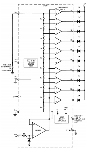
The simplifed LM3914 block diagram is to give the general idea of the circuit’s operation. A high input impedance buffer operates with signals from ground to 12V, and is protected against reverse and overvoltage signals. The signal is then applied to a series of 10 comparators; each of which is biased to a different comparison level by the resistor string.
Bar graph meter
Bar display with alarm flasher
20-step meter with single pot brightness control
Multi-step or "staging" controller
Combined controller and process deviation meter
Direction and rate indicator (to add to DVMs)
Exclamation point display for power saving
The reference is designed to be adjustable and develops a nominal 1.25V between the REF OUT (pin 7) and REF ADJ (pin 8) terminals. The reference voltage is impressed across program resistor R1 and, since the voltage is constant, a constant current I1 then flows through the output set resistor R2 giving an output voltage of
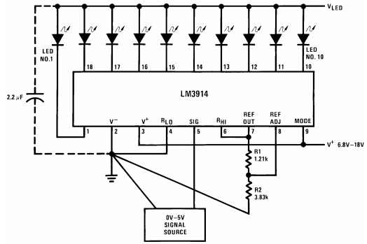
Since the 120μA current (max) is from adjust terminal represents an error term, the reference was designed to minimize changes of this current with V + and load changes.
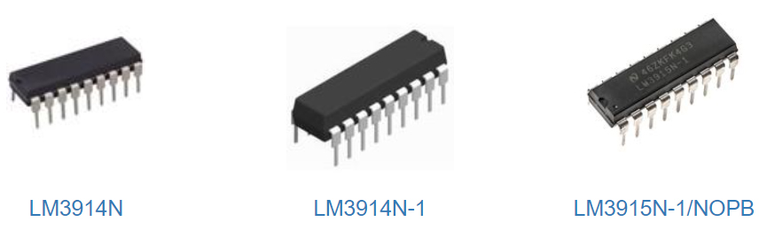
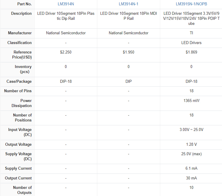
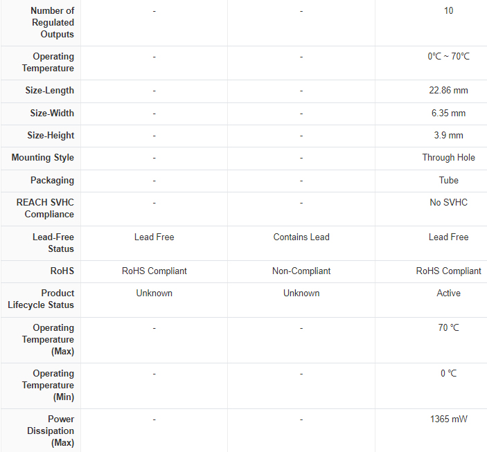
LM3914 is a linear display. LM3915 is a 3db increments logarithmic display. LM3916 is a VU-Meter display. (-20 to +3db)
The LM3914 is typically used to create a voltage display using 10 LEDs, while the LM3915 and LM3916 are typically used to display audio signal using 10 LEDs.
We are visionaries. We are differentiators. We are TIers. As a global semiconductor company operating in 35 countries, Texas Instruments (TI) is first and foremost a reflection of its people. From the TIer who unveiled the first working integrated circuit in 1958 to the more than 30,000 TIers around the world today who design, manufacture and sell analog and embedded processing chips, we are problem-solvers collaborating to change the world through technology.
Download datasheets and manufacturer documentation for Texas Instruments LM3914N-1.
Download datasheets and manufacturer documentation for LM3914N-1
TAGS
Comments