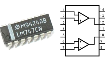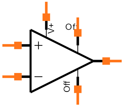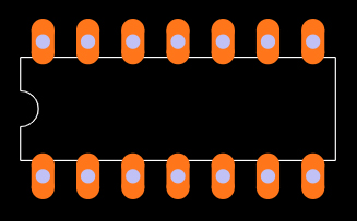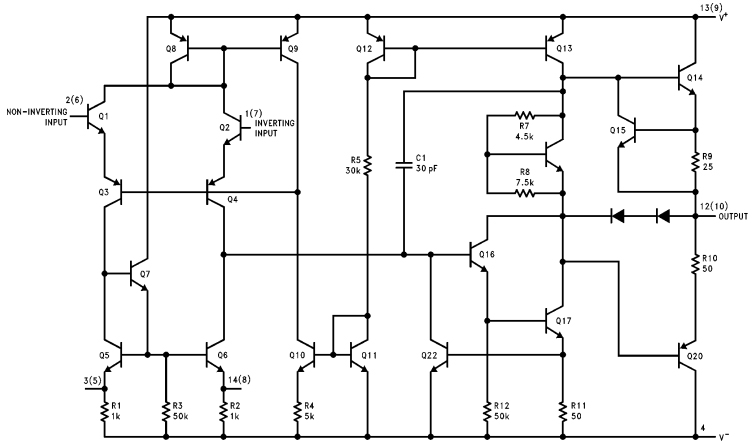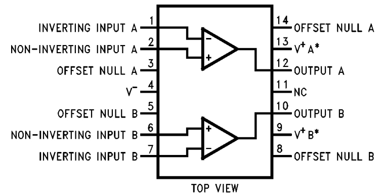
Connection Diagram
In the above connection diagram of LM747, the two op-amps in the chip can be used to design most op-amp-based circuits like voltage follower, comparator, differential amplification, and mathematical operations. And to understand the working of the device we will use a single op-amp to construct a simple microphone pre-amplifier circuit as given below.
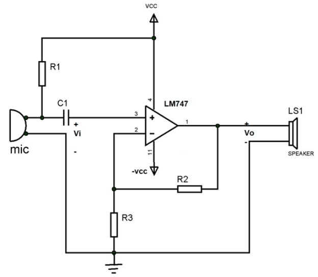
LM747 Circuit
In-circuit:
The microphone output signal is given as input to an op-amp for amplification
R1 and C1 form a high pass filter for cutting of DC signal from the microphone
The amplified output listens through the small speaker connected at the output
R2 and R3 resistors form a feedback loop for the non-inverting amplifier of the op-amp.
The equation for the output VO =Input voltage * Gain = VI * A = VI * (1+R2/R3)
For example:
Say R2 = 1MΩ, R3 = 1kΩ and microphone output voltage = 1mV
We will have voltage output VO= 1m*(1+1000) =1V approximately
This voltage appears across the speaker and we can listen to the sound. And with that, we have realized the amplifier circuit of op-amp and in a similar way, we use the device to design all other application circuits of the op-amp.