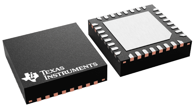
The LP5018RSMR device is an 18- or 24-channel constant-current-sink LED driver. This article is going to introduce LP5018RSMR from the perspectives of datasheet, package, manufacturer, and specification.

The LP5018RSMR device is an 18- or 24-channel constant-current-sink LED driver. This article is going to introduce LP5018RSMR from the perspectives of datasheet, package, manufacturer, and specification.
86
Mar 4, 2022
Felix Becky
The LP5018RSMR device is an 18- or 24-channel constant-current-sink LED driver. This article is going to introduce LP5018RSMR from the perspectives of datasheet, package, manufacturer, and specification.
LP5018RSMR
High-performance RGB LED drivers are required in smart homes and other applications that use human-machine interaction. Flashing, breathing, and chasing LED animation effects substantially enhance the user experience, and system noise must be kept to a minimum.
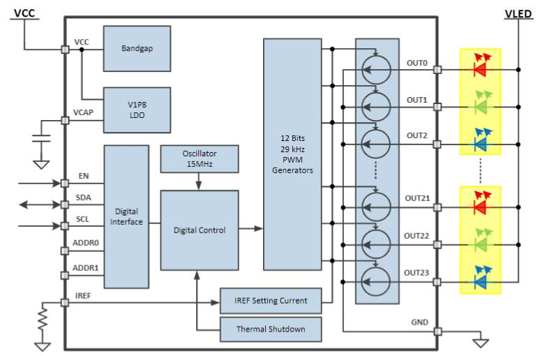
The LP5018RSMR is a constant current sink LED driver with 18 or 24 channels. Pre-configuration streamlines the software coding process for the LP5018RSMR device, which provides integrated color mixing and brightness control. For each channel, integrated 12 -bit, 29 kHz PWM generators provide smooth, vibrant color and reduce perceptible noise.
LED Lighting, Indicator Lights, and Fun Lights for:
• Smart Speaker (With Voice Assistant)
• Smart Home Appliances
• Video Doorbell
• Electronic Smart Lock
• Smoke and Heat Detector
• STB and DVR
• Smart Router
• Handheld Device
Operating Voltage Range:
– VCC Range: 2.7 V to 5.5 V
– EN, SDA, and SCL Pins Compatible With 1.8-V, 3.3-V, and 5-V Power Rails
– Output Maximum Voltage: 6 V
24 Constant-Current Sinks With High Precision
– 25.5 mA Maximum per Channel With VCC in Full Range
– 35 mA Maximum per Channel When VCC ≥ 3.3V
– Device-to-Device Error: ±7%; Channel-to channel Error: ±7%
Ultralow Quiescent Current:
– Shutdown Mode: 1 µA (Maximum) With EN Low
– Power Saving Mode: 10 µA (Typical) With EN High and All LEDs Off for > 30 ms
Integrated 12-Bit, 29-kHz PWM Generator for Each Channel:
– Independent Color-Mixing Register Per Channel
– Independent Brightness-Control Register Per RGB LED Module
– Optional Logarithmic- or Linear-Scale Brightness Control
– Integrated 3-Phase PWM-Shifting Scheme
3 Programmable Banks (R, G, B) for Easy Software Control of Each Color
2 External Hardware Address Pins Allow Connecting up to 4 Devices
Broadcast Slave Address Allows Configuring Multiple Devices Simultaneously
Auto-Increment Allows Writing or Reading Consecutive Registers Within One Transmission
Up to 400-kHz Fast-Mode I2C Speed
Symbol
Footprint
3D Models
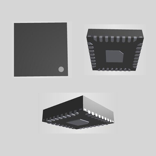
Texas Instruments LP5018RSMR technical specifications, attributes, parameters and parts with similar specifications to Texas Instruments LP5018RSMR.
| Product Attribute | Attribute Value | |
|---|---|---|
| Factory Lead Time | 12 Weeks | |
| Mounting Type | Surface Mount | |
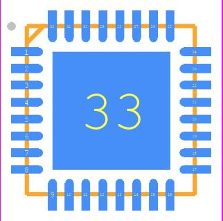
| Package / Case | 32-VFQFN Exposed Pad | |
| Surface Mount | YES | |
| Operating Temperature | -40°C~85°C TA | |
| Packaging | Tape & Reel (TR) | |
| JESD-609 Code | e4 | |
| Pbfree Code | yes | |
| Part Status | Active | |
| Moisture Sensitivity Level (MSL) | 2 (1 Year) | |
| Number of Terminations | 32Terminations | |
| Type | Linear |
| Product Attribute | Attribute Value | |
|---|---|---|
| Terminal Finish | Nickel/Palladium/Gold (Ni/Pd/Au) | |
| Applications | Lighting | |
| Terminal Position | QUAD | |
| Number of Functions | 1Function | |
| Supply Voltage | 3.3V | |
| Terminal Pitch | 0.4mm | |
| Frequency | 15MHz | |
| Base Part Number | LP5018 | |
| JESD-30 Code | S-PQCC-N32 | |
| Number of Outputs | 18Outputs | |
| Voltage - Output | 0V~5.5V | |
| Internal Switch(s) | No |
| Product Attribute | Attribute Value | |
|---|---|---|
| fmax-Min | 0.4 MHz | |
| Dimming | I2C | |
| Number of Segments | 24Segments | |
| Voltage - Supply (Max) | 5.5V | |
| Voltage - Supply (Min) | 2.7V | |
| Multiplexed Display Capability | NO | |
| Data Input Mode | SERIAL | |
| Length | 4mm | |
| Height Seated (Max) | 1mm | |
| Width | 4mm | |
| RoHS Status | ROHS3 Compliant |
| Height | 1mm |
| Length | 4mm |
| Width | 900μm |
| Thickness | 4mm |
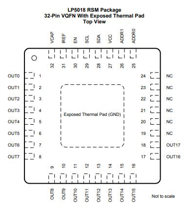
| PIN | |||
| Name | NO. | I/O | DESCRIPTION |
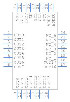
| ADDR0 | 25 | - | I²C slave-address selection pin. This pin must not be left floating. |
| ADDR1 | 26 | - | I²C slave-address selection pin. This pin must not be left floating. |
| EN | 30 | I | Chip enable input pin |
| IREF | 31 | - | Output current-reference global-setting pin |
| NC | 19,20,21, 22,23,24 |
- | No internal connection |
| OUT0 | 1 | O | Current sink output 0. If not used, this pin can be left floating. |
| OUT1 | 2 | O | Current sink output 1. If not used, this pin can be left floating. |
| OUT2 | 3 | O | Current sink output 2. If not used, this pin can be left floating. |
| OUT3 | 4 | O | Current sink output 3. If not used, this pin can be left floating. |
| OUT4 | 5 | O | Current sink output 4. If not used, this pin can be left floating. |
| OUT5 | 6 | O | Current sink output 5. If not used, this pin can be left floating. |
| OUT6 | 7 | O | Current sink output 6. If not used, this pin can be left floating. |
| OUT7 | 8 | O | Current sink output 7. If not used, this pin can be left floating. |
| OUT8 | 9 | O | Current sink output 8. If not used, this pin can be left floating. |
| OUT9 | 10 | O | Current sink output 9. If not used, this pin can be left floating. |
| OUT10 | 11 | O | Current sink output 10. If not used, this pin can be left floating. |
| OUT11 | 12 | O | Current sink output 11. If not used, this pin can be left floating. |
| OUT12 | 13 | O | Current sink output 12. If not used, this pin can be left floating. |
| OUT13 | 14 | O | Current sink output 13. If not used, this pin can be left floating. |
| OUT14 | 15 | O | Current sink output 14. If not used, this pin can be left floating. |
| OUT15 | 16 | O | Current sink output 15. If not used, this pin can be left floating. |
| OUT16 | 17 | O | Current sink output 16. If not used, this pin can be left floating. |
| OUT17 | 18 | O | Current sink output 17. If not used, this pin can be left floating. |
| SCL | 29 | I | I²C bus clock line. If not used, this pin must be connected to GND or VCC. |
| SDA | 28 | I/O | I²C bus data line. If not used, this pin must be connected to GND or VCC. |
| VCAP | 32 | - | Internal LDO output pin, this pin must be connected to a 1--µF capacitor to GND. Place the capacitor as close to the device as possible. |
| VCC | 27 | I | Input power. |
| GND | - | An exposed thermal pad also serves as the ground pin for the device. | |
1. PWM Control for Each Channel
The high-resolution PWM generator is solely utilized for intensity control in most traditional LED drivers, which are built for single-color LEDs. To obtain the desired look using RGB LEDs, however, both color mixing and intensity control must be handled. Users must manage color mixing and intensity control simultaneously with a single PWM register in the old solution. When utilizing a logarithmic scale control, several undesirable effects occur restricted dimming steps, difficult software design, and color distortion.
2. LED Bank Control
Most LED animation effects, such as blinking and breathing, use the same illumination pattern across all RGB LEDs, Instead of operating each LED individually, which consumes a lot of microcontroller resources, the LP5018RSMR device offers a simple coding solution called LED bank control.
3. Current Range Setting
A single external resistor, RIREF, controls the constant-current value (ISET) of all 24 channels. The output current is close to zero when the IREF pin is floating. The LP5018RSMR device provides internal current-limit protection when the IREF pin is shorted to GND, and the output-channel maximum current is limited to ILIM.
4. Automatic Power-Save Mode
When all of the LED outputs are turned off, the LP5018RSMR device can automatically enter power-saving mode, cutting idle current consumption to 10 A. (typical). When register bit Power Save EN = 1 (default) and all LEDs are off for more than 30 milliseconds, an automatic power-saving mode is enabled. In power-saving mode, almost all analog blocks are turned off. The LP5018RSMR device returns to NORMAL mode if any I2C commands are sent to it.
5. Protection Features-Thermal Shutdown
The thermal shutdown feature in the LP5018RSMR gadget protects the device from harm caused by overheating. The device enters shutdown mode when the junction temperature reaches 160°C (typical). When the junction temperature of the LP5018RSMR device is dropped to 145°C, the device releases thermal shutdown (typical).
| Part names | Description | Manufacturer |
| TLC5951RHAT | 24-ch 12-bit PWM LED driver w/7-bit dot correction 8-bit global brightness 40-VQFN -40 to 85 | Texas Instruments |
| TLC5952DAP | 24-channel constant-current LED driver with global brightness and LED open Short Detection 32-HTSSOP -40 to 85 | Texas Instruments |
| MAX6974ATL-T | LED Driver, BICMOS, PQCC40 | Maxim Integrated Products |
| TLC5951RHAR | 24-ch 12-bit PWM LED driver w/7-bit dot correction 8-bit global brightness 40-VQFN -40 to 85 | Texas Instruments |
| MAX6974ATL+ | LED Driver, 24-Segment, BICMOS, 6 X 6 MM, 0.80 MM EIGHT, LEAD FREE, MO-220WJJD-2, TQFN-40 | Maxim Integrated Products |
| TLC5951DAPR | 24-ch 12-bit PWM LED driver w/7-bit dot correction 8-bit global brightness 38-HTSSOP -40 to 85 | Texas Instruments |
| TLC5951RTAR | 24-ch 12-bit PWM LED driver w/7-bit dot correction 8-bit global brightness 40-WQFN -40 to 85 | Texas Instruments |
| LP5024RSMR | 24-channel I2C constant-current RGB LED driver 32-VQFN -40 to 85 | Texas Instruments |
TAGS
Comments