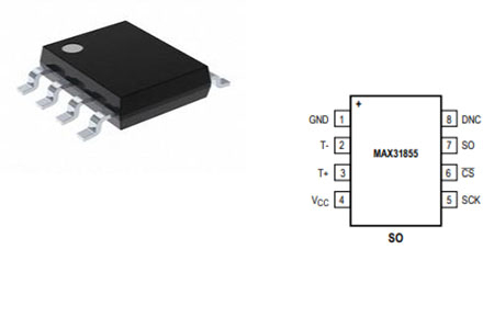
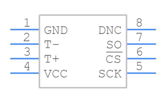
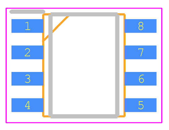
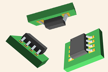
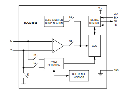
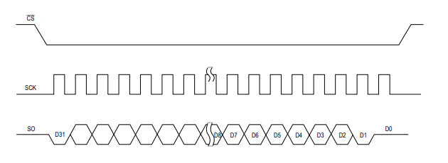
The MAX31855 is a sophisticated thermocouple-to-digital converter with a built-in 14-bit analog-to-digital converter (ADC). The device also contains cold-junction compensation sensing and correction, a digital controller, an SPIcompatible interface, and associated control logic. The device is designed to work in conjunction with an external microcontroller (µC) in thermostatic, process-control, or monitoring applications. The device is available in several versions, each optimized and trimmed for a specific thermocouple type (K, J, N, T, S, R, or E.). The thermocouple type is indicated in the suffix of the part number (e.g., MAX31855K). See the Ordering Information table for all options.
Temperature Conversion
The device includes signal-conditioning hardware to convert the thermocouple’s signal into a voltage compatible with the input channels of the ADC. The T+ and T- inputs connect to internal circuitry that reduces the introduction of noise errors from the thermocouple wires.
Before converting the thermoelectric voltages into equivalent temperature values, it is necessary to compensate for the difference between the thermocouple coldjunction side (device ambient temperature) and a 0°C virtual reference. For a K-type thermocouple, the voltage changes by about 41µV/°C, which approximates the thermocouple characteristic with the following linear equation:
VOUT = (41.276µV/°C) x (TR - TAMB)
where VOUT is the thermocouple output voltage (µV), TR is the temperature of the remote thermocouple junction (°C), and TAMB is the temperature of the device (°C). Other thermocouple types use a similar straight-line approximation but with different gain terms. Note that the MAX31855 assumes a linear relationship between temperature and voltage. Because all thermocouples exhibit some level of nonlinearity, apply appropriate correction to the device’s output data.
Cold-Junction Compensation
The function of the thermocouple is to sense a difference in temperature between two ends of the thermocouple wires. The thermocouple’s “hot” junction can be read across the operating temperature range. The reference junction, or “cold” end (which should be at the same temperature as the board on which the device is mounted) can range from -55°C to +125°C. While the temperature at the cold end fluctuates, the device continues to accurately sense the temperature difference at the opposite end.
The device senses and corrects for the changes in the reference junction temperature with cold-junction compensation. It does this by first measuring its internal die temperature, which should be held at the same temperature as the reference junction. It then measures the voltage from the thermocouple’s output at the reference junction and converts this to the noncompensated thermocouple temperature value. This value is then added to the device’s die temperature to calculate the thermocouple’s “hot junction” temperature. Note that the “hot junction” temperature can be lower than the cold junction (or reference junction) temperature.
Optimal performance from the device is achieved when the thermocouple cold junction and the device are at the same temperature. Avoid placing heat-generating devices or components near the MAX31855 because this could produce cold-junction-related errors