ATTENTION: Due to increased demand and order volume, processing time may take an additional 1-3 business days.
HomeCommunitySubjectMCP2200 Converter: Features, Pinout, and Datasheet

MCP2200 Converter: Features, Pinout, and Datasheet

Interface - Controllers 20-SOIC (0.295, 7.50mm Width) -40°C~85°C 3V~5.5V MCP2200 MICROCHIP - MCP2200-I/SO - IC, USB2.0-TO-UART, W/GPIO, 20SOIC

223

Oct 27, 2021

Cleveland Whyet

Cheap USB to UART (RS232/Serial) Converter Using Microchip MCP2200

Interface - Controllers 20-SOIC (0.295, 7.50mm Width) -40°C~85°C 3V~5.5V MCP2200 MICROCHIP - MCP2200-I/SO - IC, USB2.0-TO-UART, W/GPIO, 20SOIC

The MCP2200 is a USB-to-UART serial converter that enables USB communication in UART-equipped applications. This article mainly introduces features, pinout, datasheet and other information about Microchip Technology MCP2200.

MCP2200-I/SO

78In Stock
Min.: 1 Mult.: 1
Quantity Unit Price Ext. Price
1+ $4.089$4.09
10+ $3.85755$38.58
100+ $3.63919$363.92
500+ $3.4332$1716.6
1000+ $3.23887$3238.87
Unit Price:$4.089
Subtotal: $4.09
Looking for a better price? Want a lower wholesale price? Please send an RFQ, and we will respond immediately.
Quick Links

MCP2200 Description

The MCP2200 is a USB-to-UART serial converter that enables USB communication in UART-equipped applications. The USB termination resistors are integrated within the device, which decreases the number of external components. The MCP2200 additionally includes a 256-byte user EEPROM.

Eight general-purpose input/output pins are available on the MCP2200. Four pins serve as alternate indicators of USB and communication status.

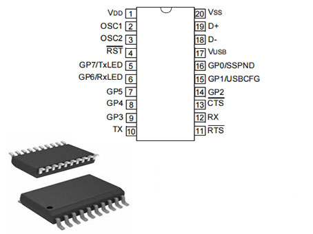
MCP2200 Pinout

Pinout


Pin Number Pin Name Description
16 GP0/SSPND General purpose I/O
15 GP1/USBCFG General purpose I/O
14 GP2 General purpose I/O
9 GP3 General purpose I/O
8 GP4 General purpose I/O
7 GP5 General purpose I/O
6 GP6/RxLED General purpose I/O
5 GP7/TxLED General purpose I/O
4 RST Reset input must be externally biased
13 CTS Hardware flow control “Clear to Send” input signal
12 RX USART RX input
11 RTS Hardware flow control “Request to Send” output
signal
10 TX USART TX output
1 VDD Power
20 VSS Ground
2 OSC1 Oscillator input
3 OSC2 Oscillator output
19 D+ USB D+
18 D- USB D- 
17 VUSB USB power pin (internally connected to 3.3V).
Should be locally bypassed with a high quality
ceramic capacitor.

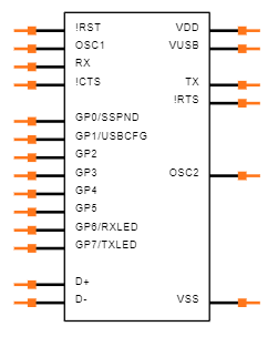
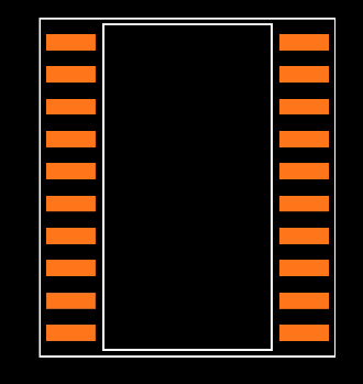
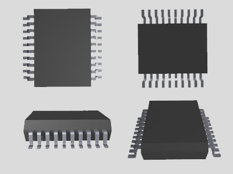
MCP2200 CAD Model

Symbol

Footprint

3D Model

MCP2200 Features

(1) Universal Serial Bus (USB)

• Supports full-speed USB (12 Mb/s)

• Implements USB protocol composite device CDC device for communications, configuration and I/O control

• 128-byte buffer to handle data throughput at any UART baud rate:

- 64 byte transmit

- 64-byte receive

• Fully configurable VID and PID assignments, and string descriptors

• Bus-powered or self-powered

• USB 2.0 Compliant (certification #: TBD)

(2) USB Driver and Software Support

• Uses standard Microsoft® Windows® drivers for Virtual Com Port (VCP):

- Windows XP(SP2 and later)/Vista/7

• Configuration utility for initial configuration

(3) Universal Asynchronous Receiver/Transmitter (UART)

• Responds to SET LINE CODING commands to dynamically change baud rates

• Supports baud rates: 300-1000k

• Hardware flow control

• UART signal polarity option

(4) General Purpose Input/Output (GPIO) Pins

• Eight (8) general-purpose I/O pins

(5) EEPROM

• 256 bytes of user EEPROM

(6) Other

• USB activity LED outputs (TxLED and RxLED)

• SSPND output pin

• USBCFG output pin (indicates if requested current is allowed)

• Operating voltage: 3.0-5.5V

• Oscillator input: 12 MHz

• ESD protection > 4 kV HBM

• Industrial (I) Operating Temperature: -40°C to +85°C

Specifications

MCP2200-I/SO Tech Specifications

Microchip Technology MCP2200-I/SO technical specifications, attributes, parameters and parts with similar specifications to Microchip Technology MCP2200-I/SO.

Product Attribute Attribute Value
Factory Lead Time7 Weeks
Contact PlatingTin
MountSurface Mount
Package / Case20-SOIC (0.295, 7.50mm Width)
Number of Pins20Pins
Weight800.987426mg
Operating Temperature-40°C~85°C
PackagingTube
JESD-609 Codee3
Pbfree Codeyes
Part StatusActive
Moisture Sensitivity Level (MSL)1 (Unlimited)
Number of Terminations20Terminations
ECCN CodeEAR99
Product Attribute Attribute Value
Voltage - Supply3V~5.5V
Terminal PositionDUAL
Terminal FormGULL WING
Peak Reflow Temperature (Cel)250
Supply Voltage3.3V
Frequency12MHz
Time@Peak Reflow Temperature-Max (s)40
Base Part NumberMCP2200
FunctionBridge, USB to UART
Operating Supply Voltage3.3V
InterfaceUART
Operating Supply Current13mA
Nominal Supply Current15mA
Logic FunctionBuffer
Product Attribute Attribute Value
Data Rate12 Mbps
ProtocolUSB
Telecom IC TypeINTERFACE CIRCUIT
ESD ProtectionYes
StandardsUSB 2.0
Number of Receivers1Receiver
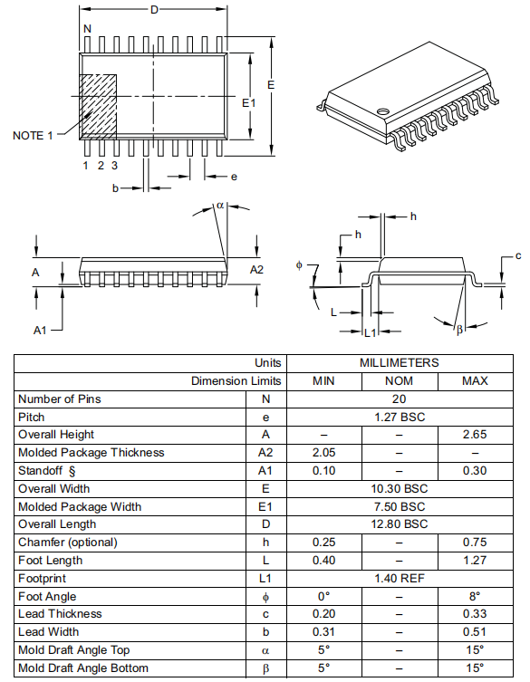
Height2.05mm
Length12.8mm
Width7.5mm
REACH SVHCNo SVHC
Radiation HardeningNo
RoHS StatusROHS3 Compliant
Lead FreeLead Free
0 Products View Similar

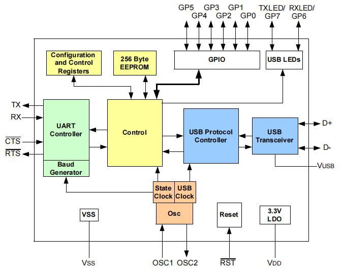
MCP2200 Functional Block Diagram

Functional Block Diagram

How to use MCP2200 Converter

There is a PCB that has an LM1117 (3.3V), Micro USB connector, MCP2200 USB-to-UART bridge, 12 MHz SMD crystal, and a few passive components.


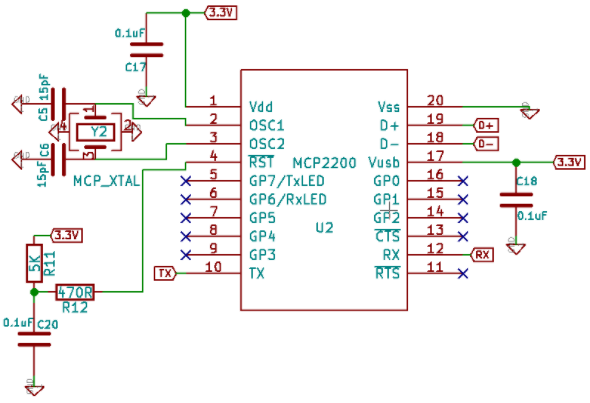
We've been watching the PCB for a few weeks and have noticed that it doesn't always work. When I connect to a machine, it occasionally displays an error message such as "USB Device not recognized" (in Windows) or "Device read/write descriptor failed" (in Linux), and then it stops working for hours before restarting. I looked through my circuit and couldn't come up with a solution to this problem. We ruled out a soldering/component issue after resoldering the board and replacing old components many times. I believe the crystal is unable to start, or that there is a race condition between the voltage at Vcc and the voltage at the RST pin, but I'm not sure how to identify the real issue and address it with MCP.


The MCP2200 schematic is provided below:

The layout of the PCB: MCP2200's Pad is in green and left side of the picture with USB connector at top left corner.


MCP2200 Oscillator

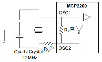
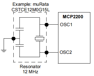
The input clock must be 12 MHz to provide the proper frequency for the USB module. USB full-speed is nominally 12 Mb/s. The clock input accuracy is ±0.25% (2,500 ppm maximum).


Quartz Crystal Operation

Ceramic Resonator Operation

MCP2200 Oscillator

The input clock must be 12 MHz to provide the proper frequency for the USB module. USB full-speed is nominally 12 Mb/s. The clock input accuracy is ±0.25% (2,500 ppm maximum).


Quartz Crystal Operation

Ceramic Resonator Operation

MCP2200 Alternatives

Part Number Description Manufacturer
MCP2200T-I/SSVAOTELECOMMUNICATION CIRCUITS Interface Circuit, PDSO20 Microchip Technology Inc
MCP2200T-I/SSTELECOMMUNICATION CIRCUITS DATACOM, INTERFACE CIRCUIT, PDSO20, 5.30 MM, LEAD FREE, PLASTIC, SSOP-20 Microchip Technology Inc
MCP2200-E/SSTELECOMMUNICATION CIRCUITS Interface Circuit, PDSO20 Microchip Technology Inc

MCP2200 Applications

• Desktop/Notebook PCs

• Multi-function Printers

• Digital TVs

• Monitors

• Consumer Audio/Video Devices

• Stand-alone Flash Media Reader/Writers

• Digital Picture Frames

• Media Players

• Set-top Boxes

• Gaming Consoles

• Automobile/Home Audio Systems

• Industrial Applications

MCP2200 Package

Package

MCP2200 Manufacturer

Microchip Technology Incorporated is a leading manufacturer of smart, networked, and secure embedded control solutions. Customers may create optimal designs using the company's simple development tools and broad product choices, which reduce risk while lowering overall system costs and time to market. The company's technologies are used by over 120,000 clients in the industrial, automotive, consumer, aerospace and defense, communications, and computing sectors. Microchip, based in Chandler, Arizona, offers outstanding technical support as well as dependable delivery and quality.

Datasheet PDF

MCP2200-I/SO Documents

Download datasheets and manufacturer documentation for MCP2200-I/SO

TAGS

Share