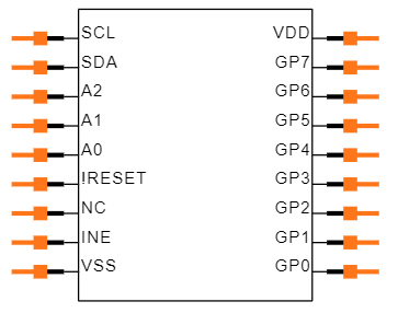
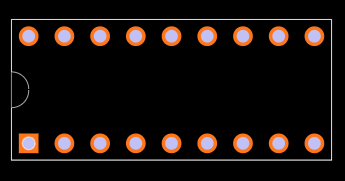
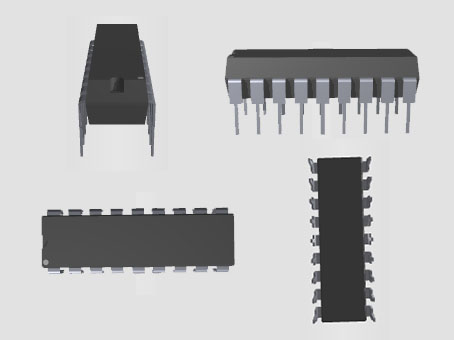
The project we'll talk about will show us how to connect an Arduino microcontroller to an MCP23008 I/O port expander.
First, we'll go over project components.
Component of Project
• These are the main components of the project.
• MCP23008 I/O Port Expander.
• A few 220Ω resistors.
• A few LEDs.
• Arduino microcontroller.
Let us now go over our projects in greater depth.
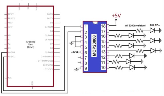
A 220 resistor and an LED are connected to each input and output pin in this circuit.
We wired +5V to Vdd and Vss to GND for the input supply.
Connect analog pin 5 of the Arduino to pin 1 of the MCP23008, which is SCL. This ensures that the Arduino and the I/O port expander chip are on the same clock.
After that, we connected SDA pin 2 of the MCP23008 to analog pin 4 of the Arduino. Data can be transferred between the Arduino and the I/O port expander chip using this connection.
Because the interrupts pin isn't used in this project, leave it disconnected.
The RESET pin is not used; instead, it is connected to +5V. If you wish to use it, simply attach it to the Arduino's digital pin, If you want to reset all of the outputs, set this pin to low in cade.
Following that, we'll ground address pins A0, A1, and A2. The address of these three pins becomes 000.
Let's look at the illustration for a better understanding.
Arduino Interfacing