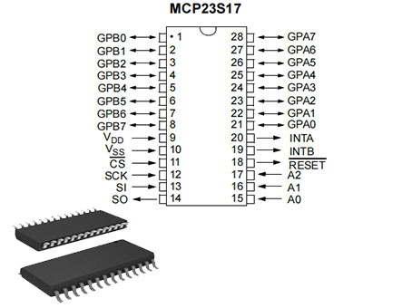
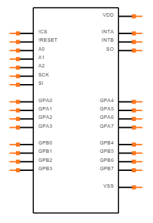
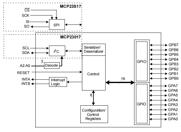
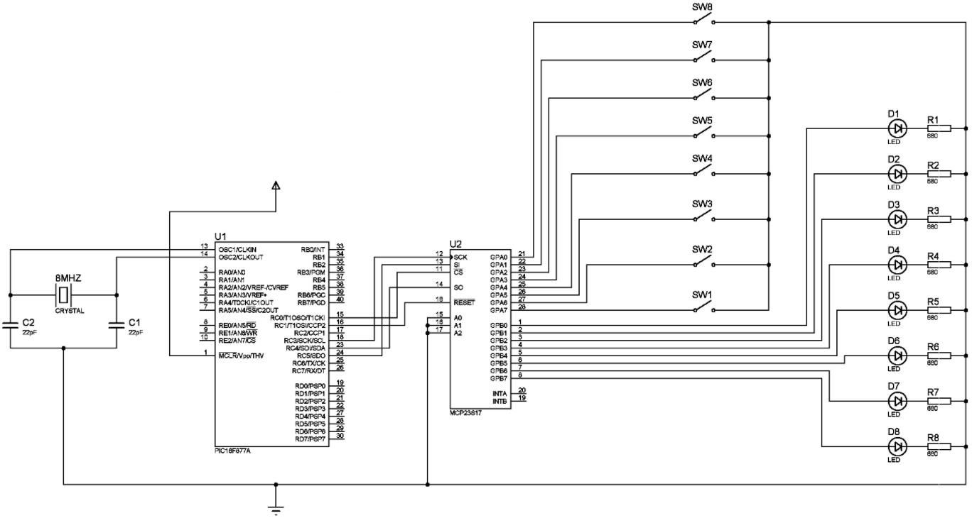
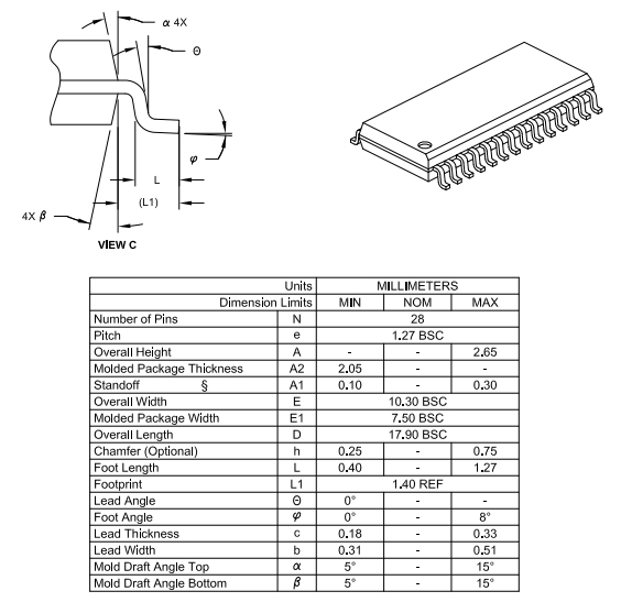
For I²C bus or SPI applications, the MCP23S17 device family enables 16-bit general-purpose parallel I/O expansion. The MCP23017 is the same as the MCP23017. The serial interface is the only difference between the two devices:
• MCP23017 – I²C interface
• MCP23S17 – SPI interface
Multiple 8-bit configuration registers for input, output and polarity selection make up the MCP23X17. By writing the I/O configuration bits (IODIRA/B), the system master can activate the I/Os as either inputs or outputs.
The data for each input or output is stored in the input or output register that corresponds to it. The Polarity Inversion register inverts the polarity of the Input Port register. The system master has access to all registers.
The 16-bit I/O port is actually two 8-bit ports connected together (PORTA and PORTB). IOCON.BANK can be used to set the MCP23X17 to work in either 8-bit or 16-bit mode.
INTA and INTB are two interrupt pins that can be linked to their respective ports or logically ORed together to activate both pins if either port triggers an interrupt.
The interrupt output can be set to activate under two (mutually exclusive) conditions:
1. When the state of any input differs from the state of the Input Port register. This is used to notify the system master when a status has changed on an input.
2. When an input state differs from a register value that has been pre-configured (DEFVAL register).
The Interrupt Capture register saves the interrupt state by capturing port values at the moment of the interrupt.
The Power-on Reset (POR) resets the device state machine and resets the registers to their default values.
To determine the device address, the hardware address pins are employed.