Arduino MCP2515 CAN Bus Interface Tutorial
IC CAN CTLR SPI 2ND GEN 20QFN
This article will unlock more details about Microchip Technology’s MCP2515, a stand-alone Controller Area Network (CAN) controller.

IC CAN CTLR SPI 2ND GEN 20QFN This article will unlock more details about Microchip Technology’s MCP2515, a stand-alone Controller Area Network (CAN) controller.
7255
Sep 6, 2021
Lionel Bessemer
1
Arduino MCP2515 CAN Bus Interface Tutorial
IC CAN CTLR SPI 2ND GEN 20QFN
This article will unlock more details about Microchip Technology’s MCP2515, a stand-alone Controller Area Network (CAN) controller.
MCP2515-E/ML

| Pin | Pin Name | Description |
| 19 | TXCAN | Transmit output pin to CAN bus |
| 20 | RXCAN | Receive input pin from CAN bus |
| 1 | CLKOUT | Clock output pin with programmable Prescaler |
| 2 | TXORTS | Transmit buffer TXB0 Request- to-Send; 100 kQ internal pul-up to VDD |
| 3 | TX1RTS | Transmit buffer TXB1 Request-to Send; 100 k22 internal pull-ups to VDD |
| 5 | TX2RTS | Transmit buffer TXB2 Request-to Send; 100 k2 internal pull-ups to VDD |
| 6 | OSC2 | Oscillator output |
| 7 | OSC1 | Oscillator input |
| 8 | Vss | Ground reference for logic and I/0 pins |
| 9 | RX1BF | Receive buffer RXB1 interrupt pin or general-purpose digital output |
| 10 | RX0BF | Receive buffer RXB0 interrupt pin or general-purpose digital output |
| 11 | NT | Interrupt output pin |
| 12 | SCK | Clock input pin for SPI interface |
| 14 | SI | Data input pin for SPI interface |
| 15 | SO | Data output pin for SPI interface |
| 16 | CS | Chip select input pin for SPI interface |
| 17 | RESET | Active-low device Reset input |
| 18 | VDD | Positive supply for logic and /0 pins |
| 4,13 | NC | No intemal connection |
| 21 | EP | Exposed Thermal Pad, connect to Vss. |
Symbol

MCP2515 Symbol
Footprint

MCP2515 Footprint
3D Model

MCP2515 3D Model
Microchip Technology MCP2515 is a stand-alone Controller Area Network (CAN) controller that implements the CAN specification, Version 2.0B. It is capable of transmitting and receiving both standard and extended data and remote frames. The MCP2515 has two acceptance masks and six acceptance filters that are used to filter out unwanted messages, thereby reducing the host MCU’s overhead. The MCP2515 interfaces with microcontrollers (MCUs) via an industry-standard Serial Peripheral Interface (SPI).
Microchip Technology MCP2515-E/ML technical specifications, attributes, parameters and parts with similar specifications to Microchip Technology MCP2515-E/ML.
Microchip Technology MCP2515-E/ML technical specifications, attributes, parameters and parts with similar specifications to Microchip Technology MCP2515-E/ML.
| Product Attribute | Attribute Value | |
|---|---|---|
| Factory Lead Time | 6 Weeks | |
| Mount | Surface Mount | |
| Package / Case | 20-VFQFN Exposed Pad | |
| Number of Pins | 20Pins | |
| Operating Temperature | -40°C~125°C | |
| Packaging | Tube | |
| Published | 2007 | |
| JESD-609 Code | e3 | |
| Pbfree Code | yes | |
| Part Status | Active | |
| Moisture Sensitivity Level (MSL) | 1 (Unlimited) | |
| Number of Terminations | 20Terminations | |
| Terminal Finish | Matte Tin (Sn) - annealed | |
| Voltage - Supply | 2.7V~5.5V |
| Product Attribute | Attribute Value | |
|---|---|---|
| Terminal Position | QUAD | |
| Terminal Form | NO LEAD | |
| Peak Reflow Temperature (Cel) | 260 | |
| Supply Voltage | 5V | |
| Terminal Pitch | 0.5mm | |
| Time@Peak Reflow Temperature-Max (s) | 40 | |
| Base Part Number | MCP2515 | |
| Function | Controller | |
| Qualification Status | Not Qualified | |
| Interface | SPI | |
| Operating Supply Current | 10mA | |
| Max Supply Current | 10mA | |
| Clock Frequency | 40MHz | |
| Protocol | CANbus |
| Product Attribute | Attribute Value | |
|---|---|---|
| Boundary Scan | NO | |
| Low Power Mode | YES | |
| Number of Transceivers | 1Transceiver | |
| Number of Serial I/Os | 1Serial I/O | |
| Standards | CAN 2.0 | |
| Data Encoding/Decoding Method | NRZ | |
| Number of Receive Buffers | 2Receive Buffers | |
| Number of Transmit Buffers | 3Transmit Buffers | |
| Height | 950μm | |
| Length | 4mm | |
| Width | 4mm | |
| REACH SVHC | No SVHC | |
| RoHS Status | ROHS3 Compliant |
• Implements CAN V2.0B at 1 Mb/s:
- 0 to 8-byte length in the data field
- Standard and extended data and remote frames
• Receive Buffers, Masks and Filters:
- Two receive buffers with prioritized message storage
- Six 29-bit filters
- Two 29-bit masks
• Data Byte Filtering on the First Two Data Bytes (applies to standard data frames)
• Three Transmit Buffers with Prioritization and Abort Features
• High-Speed SPI Interface (10 MHz):
- SPI modes 0,0 and 1,1
• One-Shot mode Ensures Message Transmission is Attempted Only One Time
• Clock Out Pin with Programmable Prescaler:
- Can be used as a clock source for other device(s)
• Start-of-Frame (SOF) Signal is Available for Monitoring the SOF Signal:
- Can be used for time slot-based protocols and/or bus diagnostics to detect early bus degradation
• Interrupt Output Pin with Selectable Enables
• Buffer Full Output Pins Configurable as:
- Interrupt output for each receive buffer
- General-purpose output
• Request-to-Send (RTS) Input Pins Individually
Configurable as:
- Control pins to request transmission for each transmit buffer
- General-purpose inputs
• Low-Power CMOS Technology:
- Operates from 2.7V-5.5V
- 5 mA active current (typical)
- 1 μA standby current (typical) (Sleep mode)
• Temperature Ranges Supported:
- Industrial (I): -40°C to +85°C
- Extended (E): -40°C to +125°C
The MCP2515 is a stand-alone CAN controller developed to simplify applications that require interfacing with a CAN bus. A simple block diagram of the MCP2515 is shown below.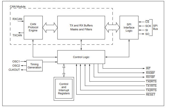
The device consists of three main blocks:
1. The CAN module, which includes the CAN protocol engine, masks, filters, transmit and receive buffers.
2. The control logic and registers that are used to configure the device and its operation.
3. The SPI protocol block.
An example system implementation using the device is shown below.
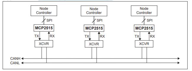
MCP2515 Example System Impementation

Microchip Technology Incorporated is a leading provider of smart, connected and secure embedded control solutions. Its easy-to-use development tools and comprehensive product portfolio enable customers to create optimal designs, which reduce risk while lowering total system cost and time to market. The company's solutions serve more than 120,000 customers across the industrial, automotive, consumer, aerospace and defence, communications and computing markets. Headquartered in Chandler, Arizona, Microchip offers outstanding technical support along with dependable delivery and quality.
Download datasheets and manufacturer documentation for MCP2515-E/ML
TAGS
Comments