ATTENTION: Due to increased demand and order volume, processing time may take an additional 1-3 business days.
HomeCommunitySubjectMCP2518FD CAN FD Controller: Features, Pinout and Datasheet

MCP2518FD CAN FD Controller: Features, Pinout and Datasheet

Interface - Controllers 14-SOIC (0.154, 3.90mm Width) -40°C~125°C 2.7V~5.5V 1.27mm 40MHz IC CAN CONTROLLER SPI 14SOIC

471

Dec 11, 2021

Jason Carl

CAN FD Explained - A Simple Intro (2020)


Interface - Controllers 14-SOIC (0.154, 3.90mm Width) -40°C~125°C 2.7V~5.5V 1.27mm 40MHz IC CAN CONTROLLER SPI 14SOIC

The MCP2518FD device is a cost-effective and small-footprint CAN FD controller that can be easily added to a microcontroller with an available SPI interface. A CAN FD channel can be easily added to a microcontroller that is either lacking a CAN FD peripheral or doesn't have enough CAN FD channels. Furthermore, Huge range of Semiconductors, Capacitors, Resistors and IcS in stock. Welcome RFQ.

MCP2518FDT-E/SL

13000In Stock
Min.: 1 Mult.: 1
Quantity Unit Price Ext. Price
1+ $1.7362$1.74
10+ $1.63793$16.38
100+ $1.54522$154.52
500+ $1.45775$728.88
1000+ $1.37524$1375.24
Unit Price:$1.7362
Subtotal: $1.74
Looking for a better price? Want a lower wholesale price? Please send an RFQ, and we will respond immediately.
Quick Links

MCP2518FD Pinout

The following figure is the diagram of MCP2518FD pinout.

Pinout

MCP2518FD CAD Model

The followings are MCP2518FD Symbol, Footprint, and 3D Model.

PCB Symbol


PCB Footprint


3D Model

MCP2518FD Overview

The MCP2518FD device is a cost-effective and small-footprint CAN FD controller that can be easily added to a microcontroller with an available SPI interface. A CAN FD channel can be easily added to a microcontroller that is either lacking a CAN FD peripheral or doesn't have enough CAN FD channels. MCP2518FD supports both CAN frames in the Classical format (CAN2.0B) and CAN Flexible Data Rate (CAN FD) format, as specified in ISO 11898-1:2015.

This article provides you with a basic overview of the MCP2518FD CAN FD Controller, including its pin descriptions, features and specifications, etc., to help you quickly understand what MCP2518FD is.

MCP2518FD Features

◆ General

    ● External CAN FD Controller with Serial Peripheral Interface (SPI)

    ● Arbitration Bit Rate up to 1 Mbps

    ● Data Bit Rate up to 8 Mbps

    ● CAN FD Controller modes

       - Mixed CAN 2.0B and CAN FD Mode

       - CAN 2.0B Mode

    ● Conforms to ISO 11898-1:2015

◆ Message FIFOs

    ● 31 FIFOs, configurable as Transmit or Receive FIFOs

    ● One Transmit Queue (TXQ)

    ● Transmit Event FIFO (TEF) with 32 bit time stamp

◆ Message Transmission

    ● Message transmission prioritization:

       - Based on priority bit field

       - Message with lowest ID gets transmitted first using the Transmit Queue (TXQ)

    ● Programmable automatic retransmission attempts: unlimited, 3 attempts or disabled

◆ Message Reception

    ● 32 Flexible Filter and Mask Objects

    ● Each object can be configured to filter either:

       - Standard ID + first 18 data bits, or

       - Extended ID

    ● 32-bit Time Stamp

◆ Special Features

    ● VDD: 2.7 to 5.5V

    ● Active Current: maximum 20 mA at 5.5 V, 40 MHz CAN clock

    ● Sleep Current: 15 μA, typical

    ● Low Power Mode current: maximum 10 μA from –40°C to 150°C

    ● Message Objects are located in RAM: 2 KB

    ● Up to 3 Configurable Interrupt Pins

    ● Bus Health Diagnostics and Error Counters

    ● Transceiver Standby Control

    ● Start of frame pin for indicating the beginning of messages on the bus

    ● Temperature Ranges:

       - Extended (E): –40°C to +125°C

       - High (H): –40°C to +150°C

◆ Oscillator Options

    ● 40, 20 or 4 MHz Crystal or Ceramic Resonator; External Clock Input

    ● Clock Output with Prescaler 

◆ SPI Interface

    ● Up to 20 MHz SPI clock speed

    ● Supports SPI Modes 0,0 and 1,1

    ● Registers and bit fields are arranged in a way to enable efficient access through SPI

◆ Safety Critical Systems

    ● SPI commands with CRC to detect noise on SPI interface

    ● Error Correction Code (ECC) protected RAM

Specifications

Microchip Technology MCP2518FDT-E/SL technical specifications, attributes, parameters and parts with similar specifications to Microchip Technology MCP2518FDT-E/SL.

MCP2518FDT-E/SL Tech Specifications

Microchip Technology MCP2518FDT-E/SL technical specifications, attributes, parameters and parts with similar specifications to Microchip Technology MCP2518FDT-E/SL.

Product Attribute Attribute Value
Factory Lead Time7 Weeks
Package / Case14-SOIC (0.154, 3.90mm Width)
Surface MountYES
Operating Temperature-40°C~125°C
PackagingTape & Reel (TR)
Part StatusActive
Moisture Sensitivity Level (MSL)3 (168 Hours)
Number of Terminations14Terminations
Voltage - Supply2.7V~5.5V
Terminal PositionDUAL
Product Attribute Attribute Value
Terminal FormGULL WING
Terminal Pitch1.27mm
JESD-30 CodeR-PDSO-G14
FunctionController
InterfaceSPI
Clock Frequency40MHz
Current - Supply20mA
ProtocolCAN
Boundary ScanNO
Low Power ModeYES
Product Attribute Attribute Value
Number of Serial I/Os1Serial I/O
StandardsCAN 2.0
Bus CompatibilitySPI
Data Transfer Rate-Max8 MBps
Length8.65mm
Height Seated (Max)1.75mm
Width3.9mm
RoHS StatusROHS3 Compliant
0 Products View Similar

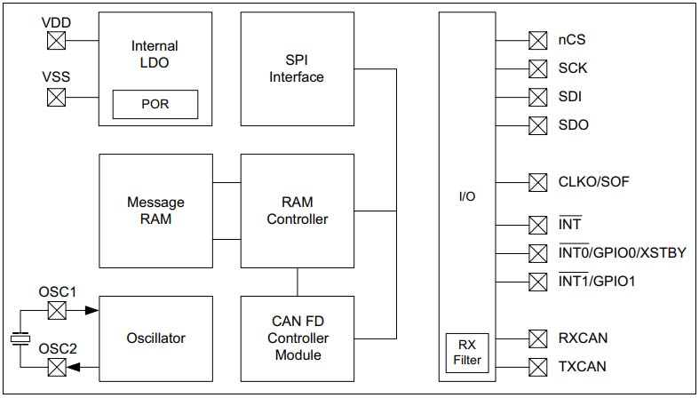
MCP2518FD Functional Block Diagram

The following is the Block Diagram of MCP2518FD.

Block Diagram

MCP2518FD Equivalent

          Model number                Manufacturer                                               Description
MCP2518FDT-H/QBB Microchip Technology Inc EEPROM
MCP2518FDT-H/SLVAO Microchip Technology Inc Serial I/O Controller, 1 Channel(s), 1MBps, CMOS, PDSO14
MCP2518FD-H/SLVAO Microchip Technology Inc Serial I/O Controller, 1 Channel(s), 1MBps, CMOS, PDSO14
MCP2518FDT-E/SLVAO Microchip Technology Inc Serial I/O Controller, 1 Channel(s), 1MBps, CMOS, PDSO14
MCP2518FDT-H/SL Microchip Technology Inc EEPROM

MCP2518FD Typical Application

MCP2518FD Interfacing with a 3.3V microcontroller

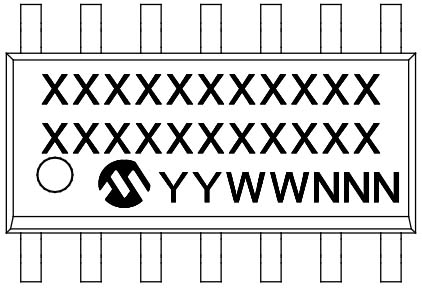
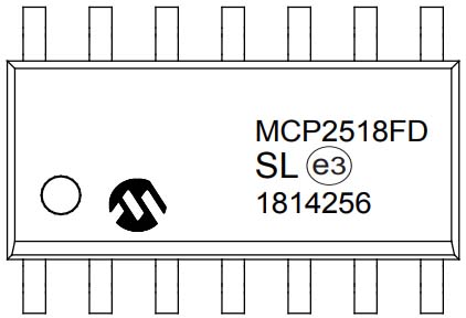
MCP2518FD Package Marking Information

The following is the Package Marking Information of MCP2518FD.

14-Lead SOIC


Example

MCP2518FD Recommended Land Pattern

The following diagram shows the MCP2518FD Recommended Land Pattern.

Recommended Land Pattern

MCP2518FD Manufacturer

Microchip Technology Inc. is a leading provider of microcontroller and analog semiconductors, providing low-risk product development, lower total system cost and faster time to market for thousands of diverse customer applications worldwide. Headquartered in Chandler, Arizona, Microchip offers outstanding technical support along with dependable delivery and quality.

Datasheet PDF

MCP2518FDT-E/SL Documents

Download datasheets and manufacturer documentation for MCP2518FDT-E/SL

Frequently Asked Questions

What is the essential property of the MCP2518FD?
The MCP2518FD device is a cost-effective and small-footprint CAN FD controller that can be easily added to a microcontroller with an available SPI interface.
The MCP2518FD device interfaces directly with microcontrollers operating at what speed?
2.7V to 5.5V.
What do the MCP2518FD device connect directly to?
The MCP2518FD device connects directly to high-speed CAN FD transceivers.
What is not required when connecting VDD of the MCP2518FD and the microcontroller to VIO of the transceiver?
There are no external level shifters required when connecting VDD of the MCP2518FD and the microcontroller to VIO of the transceiver.
How does the MCP2518FD device store message objects?
The MCP2518FD device contains a 2 KB RAM that is used to store message objects.
FAQ
What is the essential property of the MCP2518FD?
The MCP2518FD device is a cost-effective and small-footprint CAN FD controller that can be easily added to a microcontroller with an available SPI interface.
The MCP2518FD device interfaces directly with microcontrollers operating at what speed?
2.7V to 5.5V.
What do the MCP2518FD device connect directly to?
The MCP2518FD device connects directly to high-speed CAN FD transceivers.
What is not required when connecting VDD of the MCP2518FD and the microcontroller to VIO of the transceiver?
There are no external level shifters required when connecting VDD of the MCP2518FD and the microcontroller to VIO of the transceiver.
How does the MCP2518FD device store message objects?
The MCP2518FD device contains a 2 KB RAM that is used to store message objects.

TAGS

Share