ATTENTION: Due to increased demand and order volume, processing time may take an additional 1-3 business days.
HomeCommunitySubjectMCP2551 Transceiver: Circuits, Pinout, and Datasheet

MCP2551 Transceiver: Circuits, Pinout, and Datasheet

Interface - Drivers, Receivers, Transceivers 8-DIP (0.300, 7.62mm) 4.5V~5.5V -40°C~125°C MCP2551 8 2.54mm 5V MICROCHIP - MCP2551-E/P - CAN-Bus, Transceiver, CAN, seriell, 1, 1, 4.5 V, 5.5 V, DIP

14163

Nov 13, 2021

Debby Funk

CAN Communication with MCP2515, MCP2551 and AVR Microcontrollers


Interface - Drivers, Receivers, Transceivers 8-DIP (0.300, 7.62mm) 4.5V~5.5V -40°C~125°C MCP2551 8 2.54mm 5V MICROCHIP - MCP2551-E/P - CAN-Bus, Transceiver, CAN, seriell, 1, 1, 4.5 V, 5.5 V, DIP

The MCP2551 is an 8-pin DIP package high-speed CAN (Controller Area Network) transceiver. This article mainly introduces circuits, pinout, datasheet and other detailed information about Microchip Technology MCP2551.
MCP2551-E/P

960In Stock
Min.: 1 Mult.: 1
Quantity Unit Price Ext. Price
1+ $1.37163$1.37
10+ $1.29399$12.94
100+ $1.22074$122.07
500+ $1.15164$575.82
1000+ $1.08646$1086.46
Unit Price:$1.37163
Subtotal: $1.37
Looking for a better price? Want a lower wholesale price? Please send an RFQ, and we will respond immediately.
Quick Links

MCP2551 Description

The MCP2551 is an 8-pin DIP package high-speed CAN  (Controller Area Network) transceiver. This fault-tolerant CAN device acts as a link between the CAN protocol controller and the physical bus. The MCP2551  is a differential transmit and receive CAN  protocol controller that complies with all ISO-11898 specifications, including the 24V requirements. It will be capable of rates of up to 1 megabit per second. In most CAN  systems, each node requires a device to transform digital signals generated by the CAN controller into signals appropriate for transmission over the bus cabling (differential output). It also acts as a buffer between the CAN  controller and high voltage spikes on the CAN bus caused by external sources (EMI,  ESD , electrical transients). The MCP2551 CAN output can drive a minimum load of 45 ohm and can link up to 112 nodes.

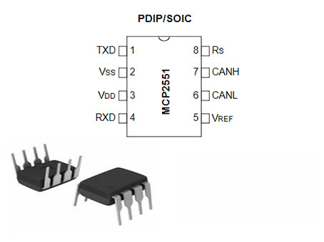
MCP2551 Pinout

Pinout


Pin Name Pin Number Description
1 TXD Transmit Data Input
2 VSS Ground
3 VDD Supply Voltage
4 RXD Receive Data Output
5 VREF Reference Output Voltage
6 CANL CAN Low-Level Voltage I/O
7 CANH CAN High-Level Voltage I/O
8 RS Slope-Control Input

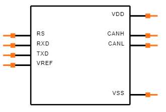
MCP2551 CAD Model

Symbol

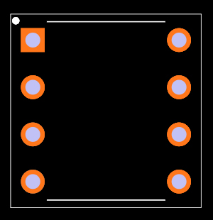
Footprint

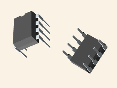
3D Model

MCP2551 Features

• Supports 1 Mb/s operation

• Implements ISO-11898 standard physical layer requirements

• Suitable for 12V and 24V systems

• Externally-controlled slope for reduced RFI emissions

• Detection of ground fault (permanent Dominant) on TXD input

• Power-on Reset and voltage brown-out protection

• An unpowered node or brown-out event will not disturb the CAN bus

• Low current standby operation

• Protection against damage due to short-circuit conditions (positive or negative battery voltage)

• Protection against high-voltage transients

• Automatic thermal shutdown protection

• Up to 112 nodes can be connected

• High-noise immunity due to differential bus implementation

• Temperature ranges:

- Industrial (I): - 40°C to +85°C

- Extended (E): -40°C to +125°C

Specifications

Microchip Technology MCP2551-E/P technical specifications, attributes, parameters and parts with similar specifications to Microchip Technology MCP2551-E/P.

MCP2551-E/P Tech Specifications

Microchip Technology MCP2551-E/P technical specifications, attributes, parameters and parts with similar specifications to Microchip Technology MCP2551-E/P.

Product Attribute Attribute Value
Factory Lead Time11 Weeks
MountThrough Hole
Mounting TypeThrough Hole
Package / Case8-DIP (0.300, 7.62mm)
Number of Pins8Pins
Operating Temperature-40°C~125°C
PackagingTube
Published1999
JESD-609 Codee3
Pbfree Codeyes
Part StatusActive
Moisture Sensitivity Level (MSL)1 (Unlimited)
Number of Terminations8Terminations
ECCN CodeEAR99
Product Attribute Attribute Value
TypeTransceiver
Terminal FinishMatte Tin (Sn)
Voltage - Supply4.5V~5.5V
Terminal PositionDUAL
Number of Functions1Function
Supply Voltage5V
Terminal Pitch2.54mm
Base Part NumberMCP2551
Pin Count8
Operating Supply Voltage5V
Power Supplies5V
InterfaceCAN, Serial
Nominal Supply Current75mA
Max Supply Current75mA
Product Attribute Attribute Value
Slew Rate8.5 V/μs
Data Rate1 Mbps
ProtocolCANbus
Number of Drivers/Receivers1/1Drivers/Receiver
DuplexHalf
Receiver Hysteresis200mV
Number of Receivers1Receiver
Height4.953mm
Length10.16mm
Width7.112mm
REACH SVHCNo SVHC
Radiation HardeningNo
RoHS StatusROHS3 Compliant
Lead FreeLead Free
0 Products View Similar

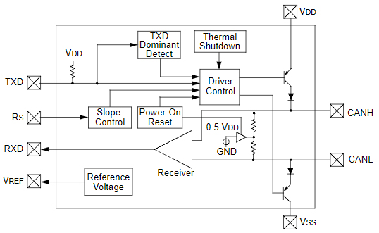
MCP2551 Functional Block Diagram

Functional Block Diagram

How to Build a CAN Transceiver Circuit with an MCP2551 Chip?

What is CAN bus ?

The CAN bus is utilized in a variety of applications, with automobiles being the most frequent. Many cars are equipped with a CAN bus, which allows them to communicate with one another.

The MCP2551 is a chip with eight pins. On the pinout part, the chip's pinout is shown.

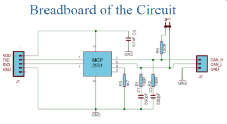
The breadboard of the circuit above is shown below.

Breadboard of the Circuit

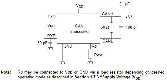
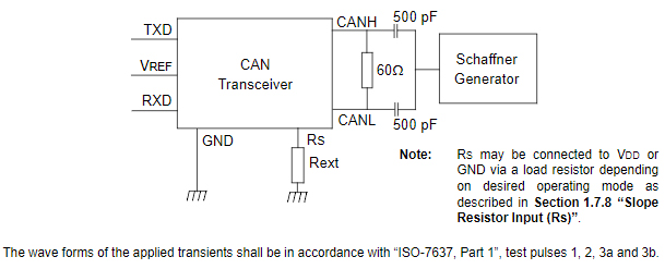
MCP2551 Test Circuit

Test Circuit for Electrical Characteristics

Test Circuit for Automotive Transients

MCP2551 Alternatives

Part Number Description Manufacturer
MCP2551-I/SNVAOTELECOMMUNICATION CIRCUITS Interface Circuit, PDSO8 Microchip Technology Inc
MCP2551-I/SNTELECOMMUNICATION CIRCUITS DATACOM, INTERFACE CIRCUIT, PDSO8, 0.150 INCH, LEAD FREE, PLASTIC, SOIC-8 Microchip Technology Inc
MCP2551-I/SNGTELECOMMUNICATION CIRCUITS DATACOM, INTERFACE CIRCUIT, PDSO8, 0.150 INCH, LEAD FREE, PLASTIC, SOIC-8 Microchip Technology Inc

MCP2551 Applications

• Automotive

• CAN Interfaces

MCP2551 Package

Package

MCP2551 Manufacturer

Microchip Technology Incorporated is a leading manufacturer of smart, networked, and secure embedded control solutions. Customers may create optimal designs using the company's simple development tools and broad product choices, which reduce risk while lowering overall system costs and time to market. The company's technologies are used by over 120,000 clients in the industrial, automotive, consumer, aerospace and defense, communications, and computing sectors. Microchip Technology Inc., based in Chandler, Arizona, offers outstanding technical assistance as well as reliable delivery and quality.

Datasheet PDF

MCP2551-E/P Documents

Download datasheets and manufacturer documentation for MCP2551-E/P

Frequently Asked Questions

1.CAN SPI MCP2515 Arduino?
The MCP2515 Module includes an MCP2515 CAN controller, which is a high-speed CAN transceiver. SPI is used to connect the MCP2515 to the MCU. As a result, it's simple to connect to any microcontroller with an SPI interface. This module is a wonderful place to start for beginners who wish to learn about CAN Bus.
2.CAN bus shield V2 adopts MCP2515 and MCP2551?
The MCP2515 CAN-BUS controller and MCP2551 CAN transceiver are still used in the CAN-BUS Shield V2. By exchanging jumpers on the DB9 interface, you can choose between OBD-II and CAN standard pinouts; OBD-II is the default. A TF card slot has been added for data storage, and the CS pin can now be changed to D4 or D5.
3.How do CAN bus system work?
"Nodes" are the devices that make up a CAN bus. Each node is made up of a CPU, a CAN controller, and a transceiver that adjusts the signal levels of data broadcast and received. Data can be sent and received by all nodes, but not at the same time. Data cannot be sent directly between nodes.
FAQ
1.CAN SPI MCP2515 Arduino?
The MCP2515 Module includes an MCP2515 CAN controller, which is a high-speed CAN transceiver. SPI is used to connect the MCP2515 to the MCU. As a result, it's simple to connect to any microcontroller with an SPI interface. This module is a wonderful place to start for beginners who wish to learn about CAN Bus.
2.CAN bus shield V2 adopts MCP2515 and MCP2551?
The MCP2515 CAN-BUS controller and MCP2551 CAN transceiver are still used in the CAN-BUS Shield V2. By exchanging jumpers on the DB9 interface, you can choose between OBD-II and CAN standard pinouts; OBD-II is the default. A TF card slot has been added for data storage, and the CS pin can now be changed to D4 or D5.
3.How do CAN bus system work?
"Nodes" are the devices that make up a CAN bus. Each node is made up of a CPU, a CAN controller, and a transceiver that adjusts the signal levels of data broadcast and received. Data can be sent and received by all nodes, but not at the same time. Data cannot be sent directly between nodes.

TAGS

Share