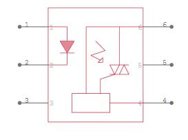
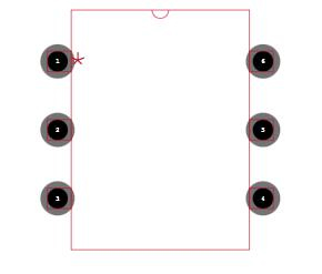
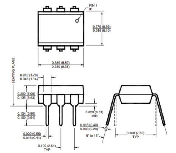
The MOC3041 is frequently used in AC motor speed control, light dimmers, and other home automation applications that involve an AC load. The following is a typical application circuit schematic for controlling an ACload with a Microcontroller.

MOC3041 Application Circuit
Pins 1 and 2 are connected to the internal IR LED. Through the resistor Rin, the voltage source Vcc should be able to provide 15mA to the LED's Anode pin. Based on a PWM signal from the microcontroller, the NAND gate connects the LED's Cathode pin to the ground. As a result, one input pin of the NAND gate will be linked to the ground and the other to the PWM signal.
The LED will be turned on at a specific interval based on the PWM signal, and the internal TRIAC will also be switched on. When the internal TRIAC is turned on, the external TRIAC is switched on, and the AC load is controlled. The 0.01uF capacitors and the 39 ohms resistor comprise an optional Snubber circuit. As a result, the output voltage varies depending on the duty cycle of the PWM, allowing us to adjust the load's speed and intensity.