Initial Experiments with the MPF102 JFET
The MPF102 is a popular N-Channel JFET that is commonly used in low power amplification applications or electronic switching applications such as low ON resistance analog switching.

The MPF102 is a popular N-Channel JFET that is commonly used in low power amplification applications or electronic switching applications such as low ON resistance analog switching.
2066
Aug 23, 2021
Lee Rockefeller
Initial Experiments with the MPF102 JFET
The MPF102 is a popular N-Channel JFET that is commonly used in low power amplification applications or electronic switching applications such as low ON resistance analog switching.
MPF102
The MPF102 is a popular N-Channel JFET that is commonly used in low power amplification applications or electronic switching applications such as low ON resistance analog switching. It can be used for amplification in the VHF region of frequencies and other audio amplification-related applications. The MPF102 possesses high gain and low noise features which make it ideal to use for the amplification of very small or low-level signals like the RF signal, audio signal, etc.
Sadly, the MPF102 is no longer in production. You can find it in some suppliers that still have them in stock or you can replace them with other new designs like J113, NTE457, etc.
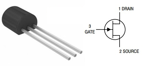
Symbol
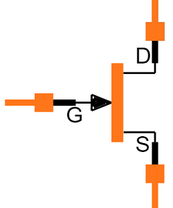
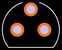
Footprint
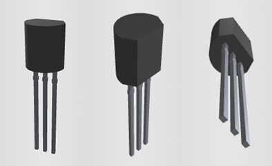
3D Model

Transistor Type: JFET N Channel
Package Type: TO-92
Max Drain to Source Voltage: 25 V
Max Drain to Gate Voltage: 25 V
Max Gate to Source Voltage: -25 V
Max Continues Gate Current: 10 mA
Max Power Dissipation: 350 mW
Storage temperature range: -65 to +150 Centigrade
Low Noise & High Gain
ON Semiconductor MPF102 technical specifications, attributes, parameters and parts with similar specifications to ON Semiconductor MPF102.
ON Semiconductor MPF102 technical specifications, attributes, parameters and parts with similar specifications to ON Semiconductor MPF102.
| Product Attribute | Attribute Value | |
|---|---|---|
| Lifecycle Status | OBSOLETE (Last Updated: 1 day ago) | |
| Mount | Through Hole | |
| Package / Case | TO-92 | |
| Number of Pins | 3Pins | |
| Weight | 201mg | |
| Number of Elements | 1 Element | |
| Power Dissipation (Max) | 350mW | |
| Packaging | Bulk | |
| JESD-609 Code | e0 | |
| Pbfree Code | no | |
| Number of Terminations | 3Terminations | |
| Terminal Finish | Tin/Lead (Sn/Pb) | |
| Max Operating Temperature | 155°C |
| Product Attribute | Attribute Value | |
|---|---|---|
| Min Operating Temperature | -55°C | |
| HTS Code | 8541.21.00.95 | |
| Voltage - Rated DC | 25V | |
| Terminal Position | BOTTOM | |
| Peak Reflow Temperature (Cel) | 240 | |
| Current Rating | 10mA | |
| Time@Peak Reflow Temperature-Max (s) | 30 | |
| Pin Count | 3 | |
| Qualification Status | Not Qualified | |
| Element Configuration | Single | |
| Operating Mode | DEPLETION MODE | |
| Power Dissipation | 350mW | |
| Transistor Application | AMPLIFIER |
| Product Attribute | Attribute Value | |
|---|---|---|
| Drain to Source Voltage (Vdss) | 15V | |
| Polarity/Channel Type | N-CHANNEL | |
| Continuous Drain Current (ID) | 20mA | |
| Gate to Source Voltage (Vgs) | -25V | |
| Drain to Source Breakdown Voltage | 25V | |
| FET Technology | JUNCTION | |
| Highest Frequency Band | VERY HIGH FREQUENCY B | |
| Height | 4.58mm | |
| Length | 4.58mm | |
| Width | 3.86mm | |
| RoHS Status | RoHS Compliant | |
| Lead Free | Lead Free |
BF245C, BF245B, 2N5457, 2N5458, NTE457, J113, 2N3819, 2N4416, NTE312, 2N5638, 2N5640, 2SK162, 2SK518
Please check the pin configuration and parameters before replacing them in your circuit.
The MPF102 can be used in various amplification and switching applications. Its high gain and low noise features make it ideal to be used for the amplification of very small signals. The MPF102 can be used in signal booster circuits, audio preamplifier circuits, and audio amplifier stages, etc. As a switch, the MPF102 can be used to drive loads under 10mA such as in low ON resistance analog switching.
A JEFT is considered "ON" by default, that is even if there is no voltage applied to its gate and source terminals, the JFET will still allow current to flow from Drain to Source. In order to stop the JEFT from conducting current, a negative gate voltage has to be applied to the gate pin, for the MPF102 it should be typically -7.5V.
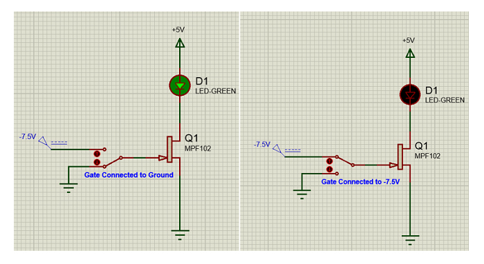
The images above showed how a load (LED) can be toggled using a JFET like MPF102. When the gate pin is grounded, the JFET allows current to flow from Drain to Source, and thus the LED is turned on. When it is biased using -7.5V on the gate pin, the JFET blocks the flow of current between the Drain and Source pin and thus turns off the LED.
VHF signal amplifier
Low-level signal amplifier
Audio preamplifiers
Sensor circuits
Audio amplifier stages
Audio noise cancellation
Low ON resistance analog switching
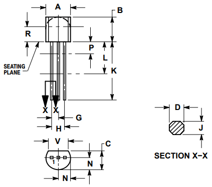
MPF102 Package Outline
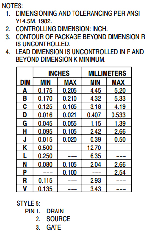
MPF102 Mechanical Data
ON Semiconductor (Nasdaq: ON) is driving energy-efficient innovations, empowering customers to reduce global energy use. The company offers a comprehensive portfolio of energy-efficient power and signal management, logic, discrete and custom solutions to help design engineers solve their unique design challenges in automotive, communications, computing, consumer, industrial, LED lighting, medical, military/aerospace, and power supply applications. ON Semiconductor operates a responsive, reliable, world-class supply chain and quality program, and a network of manufacturing facilities, sales offices, and design centers in key markets throughout North America, Europe, and the Asia Pacific regions.
Download datasheets and manufacturer documentation for ON Semiconductor MPF102.
Download datasheets and manufacturer documentation for MPF102
TAGS
Comments