ATTENTION: Due to increased demand and order volume, processing time may take an additional 1-3 business days.
HomeCommunitySubjectMPU9250 Digital Motion Processor: Datasheet, Pinout, MPU9250 vs. MPU6050

MPU9250 Digital Motion Processor: Datasheet, Pinout, MPU9250 vs. MPU6050

IMU ACCEL/GYRO/MAG I2C/SPI 24QFN The MPU9250 9-axis Digital Motion Processor is a combined processor of the 3-axis gyroscope, 3-axis accelerometer, and the 3-axis Magnetometer.

397

Sep 26, 2021

Natalie Tate

How to use MPU-9250 Gyroscope, Accelerometer, Magnetometer for Arduino


IMU ACCEL/GYRO/MAG I2C/SPI 24QFN

The MPU9250 9-axis Digital Motion Processor is a combined processor of the 3-axis gyroscope, 3-axis accelerometer, and the 3-axis Magnetometer. This article will unlock more details about MPU9250, furthermore, there is a huge range of Semiconductors, Capacitors, Resistors and ICs in stock. Welcome RFQ.

MPU-9250

1000In Stock
Min.: 1 Mult.: 1
Price not displayed? Not available to buy online? Please send an RFQ, and we will respond immediately.
Quick Links

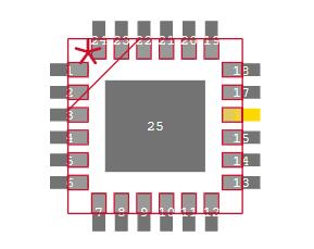
MPU9250 Pinout

MPU9250 Pinout


Pin   Number Pin Name Descriptions
1 RESV Reserved. Connect to VDDIO.
7 AUX_CL I2C Master serial clock, for   connecting to external sensors
8 VDDIO Digital I/O supply voltage
9 AD0 /SDO I2C Slave Address LSB (AD0); SPI   serial data output (SDO)
10 REGOUT Regulator filter capacitor connection
11 FSYNC Frame synchronization digital input.   Connect to GND if unused
12 INT Interrupt digital output (totem pole   or open-drain)
13 VDD Power supply voltage and Digital I/O   supply voltage
18 GND Power supply ground
19 RESV Reserved. Do not connect
20 RESV Reserved. Connect to GND
21 AUX_DA I2C master serial data, for connecting   to external sensors
22 nCS Chip select (SPI mode only)
23 SCL / SCLK I2C serial clock (SCL); SPI serial   clock (SCLK)
24 SDA / SDI I2C serial data (SDA); SPI serial data   input (SDI)
2-6,   14-17 NC Not internally connected. May be used for PCB trace routing.

Pin Description

MPU9250 CAD Model

MPU9250 Symbol


MPU9250 Footprint


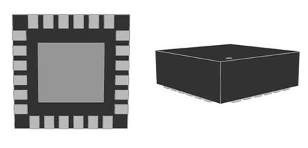
MPU9250  3D Model

MPU9250 Overview

The InvenSense MPU9250 9-axis Digital Motion Processor is a combined processor of the 3-axis gyroscope, 3-axis accelerometer, and the 3-axis Magnetometer. The DMP has three 16-bit resolution analogue-to-digital Converters for the digitization of the outputs from the accelerometer, magnetometer, and gyroscope. The device also has a separate power supply for digital I/O, an integrated temperature sensor, and programmable interrupts.


Specifications

TDK InvenSense MPU-9250 technical specifications, attributes, parameters and parts with similar specifications to TDK InvenSense MPU-9250.

MPU-9250 Tech Specifications

TDK InvenSense MPU-9250 technical specifications, attributes, parameters and parts with similar specifications to TDK InvenSense MPU-9250.

Product Attribute Attribute Value
Factory Lead Time16 Weeks
MountSurface Mount
Mounting TypeSurface Mount
Package / Case24-TFQFN Module Exposed Pad
Number of Pins25Pins
Supplier Device Package24-QFN (3x3)
Operating Temperature-40°C~85°C TA
PackagingTape & Reel (TR)
Product Attribute Attribute Value
SeriesMotionTracking™
Published2012
Part StatusObsolete
Moisture Sensitivity Level (MSL)3 (168 Hours)
Max Operating Temperature85°C
Min Operating Temperature-40°C
Output TypeI2C, SPI
InterfaceI2C, SPI
Product Attribute Attribute Value
Max Supply Voltage3.6V
Min Supply Voltage2.4V
Sensor TypeAccelerometer, Gyroscope, Magnetometer, 9 Axis
Height1mm
Length3.1mm
Width3.1mm
RoHS StatusRoHS Compliant
0 Products View Similar

MPU9250 Feature

1. Gyroscope Features

The triple-axis MEMS gyroscope in the MPU-9250 includes a wide range of features:

 Digital-output X-, Y-, and Z-Axis angular rate sensors (gyroscopes) with a user-programmable fullscale range of ±250, ±500, ±1000, and ±2000°/sec and integrated 16-bit ADCs

 Digitally-programmable low-pass filter

 Gyroscope operating current: 3.2mA

 Sleep mode current: 8µA

 Factory calibrated sensitivity scale factor

 Self-test

2. Accelerometer Features

The triple-axis MEMS accelerometer in MPU-9250 includes a wide range of features:

 Digital-output triple-axis accelerometer with a programmable full scale range of ±2g, ±4g, ±8g and ±16g and integrated 16-bit ADCs

 Accelerometer normal operating current: 450µA

 Low power accelerometer mode current: 8.4µA at 0.98Hz, 19.8µA at 31.25Hz

 Sleep mode current: 8µA

 User-programmable interrupts

 Wake-on-motion interrupt for low power operation of applications processor

 Self-test

3. Magnetometer Features

The triple-axis MEMS magnetometer in MPU-9250 includes a wide range of features:

 3-axis silicon monolithic Hall-effect magnetic sensor with magnetic concentrator

 Wide dynamic measurement range and high resolution with lower current consumption.

 Output data resolution of 14 bit (0.6µT/LSB)

 Full-scale measurement range is ±4800µT

 Magnetometer normal operating current: 280µA at 8Hz repetition rate

 Self-test function with an internal magnetic source to confirm magnetic sensor operation on end products

4. Additional Features

The MPU-9250 includes the following additional features:

 Auxiliary master I2C bus for reading data from external sensors (e.g. pressure sensor)

 3.5mA operating current when all 9 motion sensing axes and the DMP are enabled

 VDD supply voltage range of 2.4 – 3.6V

 VDDIO reference voltage for auxiliary I2C devices

 Smallest and thinnest QFN package for portable devices: 3x3x1mm

 Minimal cross-axis sensitivity between the accelerometer, gyroscope and magnetometer axes

 512 byte FIFO buffer enables the applications processor to read the data in bursts

 Digital-output temperature sensor

 User-programmable digital filters for gyroscope, accelerometer, and temp sensor

 10,000 g shock tolerant

 400kHz Fast Mode I2C for communicating with all registers

 1MHz SPI serial interface for communicating with all registers

MPU9250 Application

  • Location-based services, points of interest, and dead reckoning

  • Handset and portable gaming

  • Motion-based game controllers

  • 3D remote controls for Internet-connected DTVs and set-top boxes, 3D mice

  • Wearable sensors for health, fitness, and sports

MPU9250 Block Diagram

MPU9250 Block Diagram

MPU9250 Typical Operation Circuit

MPU9250 Typical Operating Circuit

MPU9250 Interfacing Diagram

The Interfacing Diagram for MPU9250 is given below.

MPU9250 Interfacing Diagram


How to Interface MPU9250 DMP with Microcontroller?

  1. In order to communicate with the module, the microcontroller must support at least one of the serial protocols SPI or I2C.

  2. The power supply pins are used to power the module.

  3. Connect the microcontroller's analogue pins to the Serial data line (SDA) and Serial clock line (SCA). The data will be transmitted using the I2C protocol.

  4. For communication, the module also contains a Serial Peripheral Interface.

  5. If the microcontroller in question does not use any, make sure to include pull up resistors to prevent I2C signal loss.

MPU9250 Package

MPU9250 Manufacturer

InvenSense, Inc is a Group Company that provides TDK products. As a part of the Sensor System Business Company and the industry leader around the world, InvenSense is dedicated to MEMS Motion, Audio, and Pressure Solutions, industrial, automotive, and IoT market segments. Due to the stronger portfolio of MEMS 3/6/7/9 axis motion sensors and their high-performance MEMS audio microphones, and pressure sensors,they are far ahead of the rest of the world. TDK keeps pushing the boundaries of performance and quality. In the meantime, they keep setting new standards of innovation for multiple industries.

Datasheet PDF

MPU-9250 Documents

Download datasheets and manufacturer documentation for MPU-9250

Frequently Asked Questions

How accurate is MPU-9250?
However, after applying our improved calibration techniques, even our worst-performing MPU9250 board with very large magnetometer offset biases showed a heading accuracy of 2.2 degrees RMS. This is perfectly adequate for many applications.
How do I connect my MPU9250?
Embed the widget on your own site Step 1: Components. Step 2: Connect the MPU9250 Accelerometer Gyroscope Compass to Arduino. Step 3: Start Visuino, and select the Arduino Board type. Step 4: In Visuino: Add and connect the MPU9250 component. Step 5: In Visuino: Add and connect the Packet component.
How do I calibrate my MPU9250?
During calibration, ensure that the hardware is stable. Hold the hardware stable and press ENTER to start the calibration. For more information, see Calibrate the Accelerometer in the MPU-9250 Sensor. Hold the hardware with its z-axis pointing upwards and press ENTER.
FAQ
How accurate is MPU-9250?
However, after applying our improved calibration techniques, even our worst-performing MPU9250 board with very large magnetometer offset biases showed a heading accuracy of 2.2 degrees RMS. This is perfectly adequate for many applications.
How do I connect my MPU9250?
Embed the widget on your own site Step 1: Components. Step 2: Connect the MPU9250 Accelerometer Gyroscope Compass to Arduino. Step 3: Start Visuino, and select the Arduino Board type. Step 4: In Visuino: Add and connect the MPU9250 component. Step 5: In Visuino: Add and connect the Packet component.
How do I calibrate my MPU9250?
During calibration, ensure that the hardware is stable. Hold the hardware stable and press ENTER to start the calibration. For more information, see Calibrate the Accelerometer in the MPU-9250 Sensor. Hold the hardware with its z-axis pointing upwards and press ENTER.

TAGS

Share