How a 555 Timer IC Works
STMICROELECTRONICS - NE555N - TIMER
The NE555N monolithic timing circuit is a highly stable controller capable of producing accurate time delays or oscillation.

STMICROELECTRONICS - NE555N - TIMER
298
Jul 7, 2021
Stanford Joyce
How a 555 Timer IC Works
STMICROELECTRONICS - NE555N - TIMER
The NE555N monolithic timing circuit is a highly stable controller capable of producing accurate time delays or oscillation.
NE555N
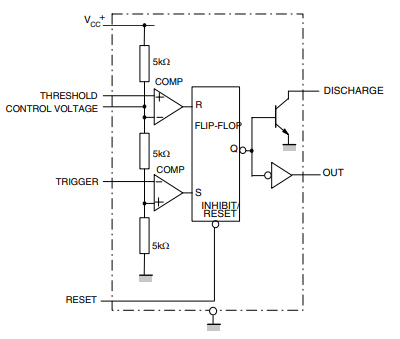
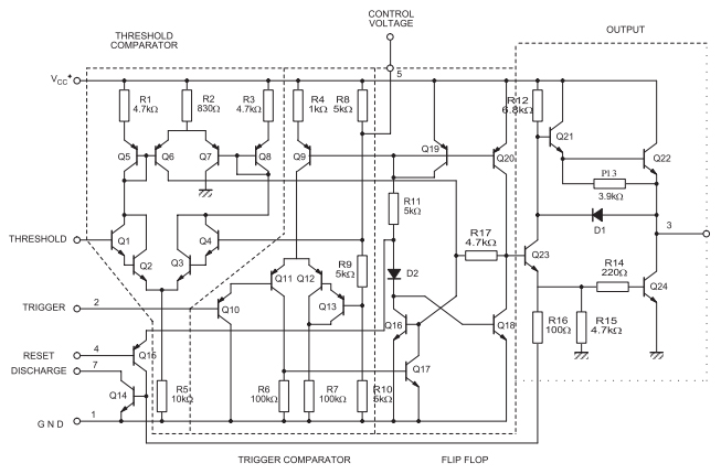
The NE555N monolithic timing circuit is a highly stable controller capable of producing accurate time delays or oscillation. In the time delay mode of operation, the time is precisely controlled by one external resistor and capacitor. For a stable operation as an oscillator, the free running frequency and the duty cycle are both accurately controlled with two external resistors and one capacitor. The circuit may be triggered and reset on falling waveforms, and the output structure can source or sink up to 200 mA.
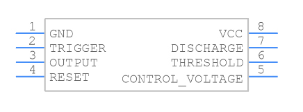
Symbol
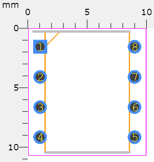
Footprint
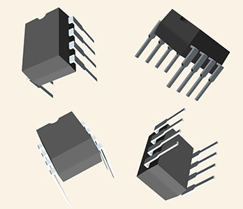
3D Model
Low turn-off time
Maximum operating frequency greater than 500 kHz
Timing from microseconds to hours
Operates in both astable and monostable modes
Output can source or sink up to 200 mA
Adjustable duty cycle
TTL compatible
Temperature stability of 0.005% per °C
Normally on and normally off output
Direct replacement for SE555/NE555
STMicroelectronics NE555N technical specifications, attributes, parameters and parts with similar specifications to STMicroelectronics NE555N.
STMicroelectronics NE555N technical specifications, attributes, parameters and parts with similar specifications to STMicroelectronics NE555N.
| Product Attribute | Attribute Value | |
|---|---|---|
| Mount | Through Hole | |
| Mounting Type | Through Hole | |
| Package / Case | 8-DIP (0.300, 7.62mm) | |
| Number of Pins | 8Pins | |
| Weight | 4.535924g | |
| Operating Temperature | 0°C~70°C | |
| Packaging | Tube | |
| JESD-609 Code | e3 | |
| Pbfree Code | yes | |
| Part Status | Obsolete | |
| Moisture Sensitivity Level (MSL) | 1 (Unlimited) | |
| Number of Terminations | 8Terminations |
| Product Attribute | Attribute Value | |
|---|---|---|
| ECCN Code | EAR99 | |
| Type | 555 Type, Timer/Oscillator (Single) | |
| Terminal Finish | Matte Tin (Sn) - annealed | |
| Voltage - Supply | 5V | |
| Terminal Position | DUAL | |
| Number of Functions | 1Function | |
| Terminal Pitch | 2.54mm | |
| Frequency | 500kHz | |
| Base Part Number | NE555 | |
| Pin Count | 8 | |
| Number of Channels | 1Channel | |
| Nominal Supply Current | 10mA |
| Product Attribute | Attribute Value | |
|---|---|---|
| Output Current | 200mA | |
| Current - Supply | 10mA | |
| High Level Output Current | -200mA | |
| Low Level Output Current | 200mA | |
| Min Supply Voltage (DC) | 4.5V | |
| Height | 3.3mm | |
| Length | 9.27mm | |
| Width | 6.35mm | |
| REACH SVHC | No SVHC | |
| Radiation Hardening | No | |
| RoHS Status | ROHS3 Compliant | |
| Lead Free | Lead Free |
In the monostable mode, the timer generates a single pulse. As shown in Figure 1, the external capacitor is initially held discharged by a transistor inside the timer.
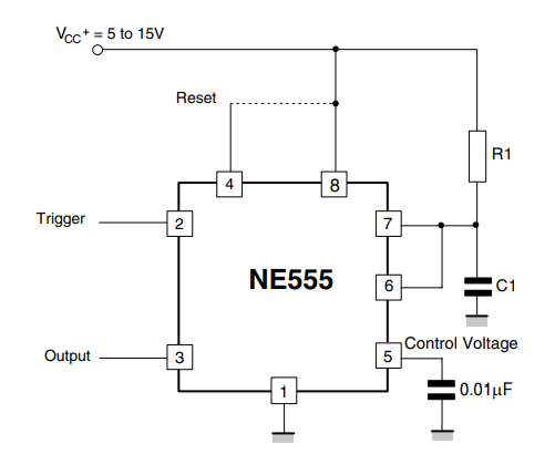
Figure 1. NE555N typical schematics in monostable operation
The circuit triggers on a negative-going input signal when the level reaches 1/3 VCC. Once triggered, the circuit remains in this state until the set time has elapsed, even if it is triggered again during this interval. The duration of the output HIGH state is given by t = 1.1 R1C1 and is easily determined by Figure 3.
Note that because the charge rate and the threshold level of the comparator are both directly proportional to supply voltage, the timing interval is independent of supply. Applying a negative pulse simultaneously to the reset terminal (pin 4) and the trigger terminal (pin 2) during the timing cycle discharges the external capacitor and causes the cycle to start over. The timing cycle now starts on the positive edge of the reset pulse. During the time the reset pulse is applied, the output is driven to its LOW state.
When a negative trigger pulse is applied to pin 2, the flip-flop is set, releasing the shortcircuit across the external capacitor and driving the output HIGH. The voltage across the capacitor increases exponentially with the time constant t = R1C1. When the voltage across the capacitor equals 2/3 VCC, the comparator resets the flip-flop which then discharges the capacitor rapidly and drives the output to its LOW state.
Figure 2 shows the actual waveforms generated in this mode of operation.
When Reset is not used, it should be tied high to avoid any possibility of unwanted triggering.

Figure 2. NE555N waveforms in monostable operation
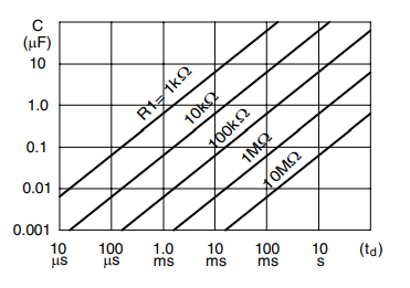
Figure 3. NE555N pulse duration versus R1C1
Precision timing
Pulse generation
Sequential timing
Time delay generation
Pulse width modulation
Pulse position modulation
Linear ramp generator
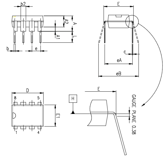
NE555N Package Outline
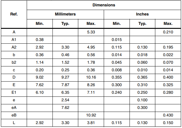
NE555N Mechanical Data
STMicroelectronics is a global independent semiconductor company and is a leader in developing and delivering semiconductor solutions across the spectrum of microelectronics applications. An unrivaled combination of silicon and system expertise, manufacturing strength, Intellectual Property (IP) portfolio and strategic partners positions the Company at the forefront of System-on-Chip (SoC) technology and its products play a key role in enabling today's convergence trends.
Download datasheets and manufacturer documentation for STMicroelectronics NE555N.
Download datasheets and manufacturer documentation for NE555N
TAGS
Comments